Since the last post lots of progress has been made! Rudder Stops were riveted on, Flap Motor was installed, and significant progress has been made on the rudder control system. Nothing extremely complicated but definitely a few head scratchers that I had to work through.
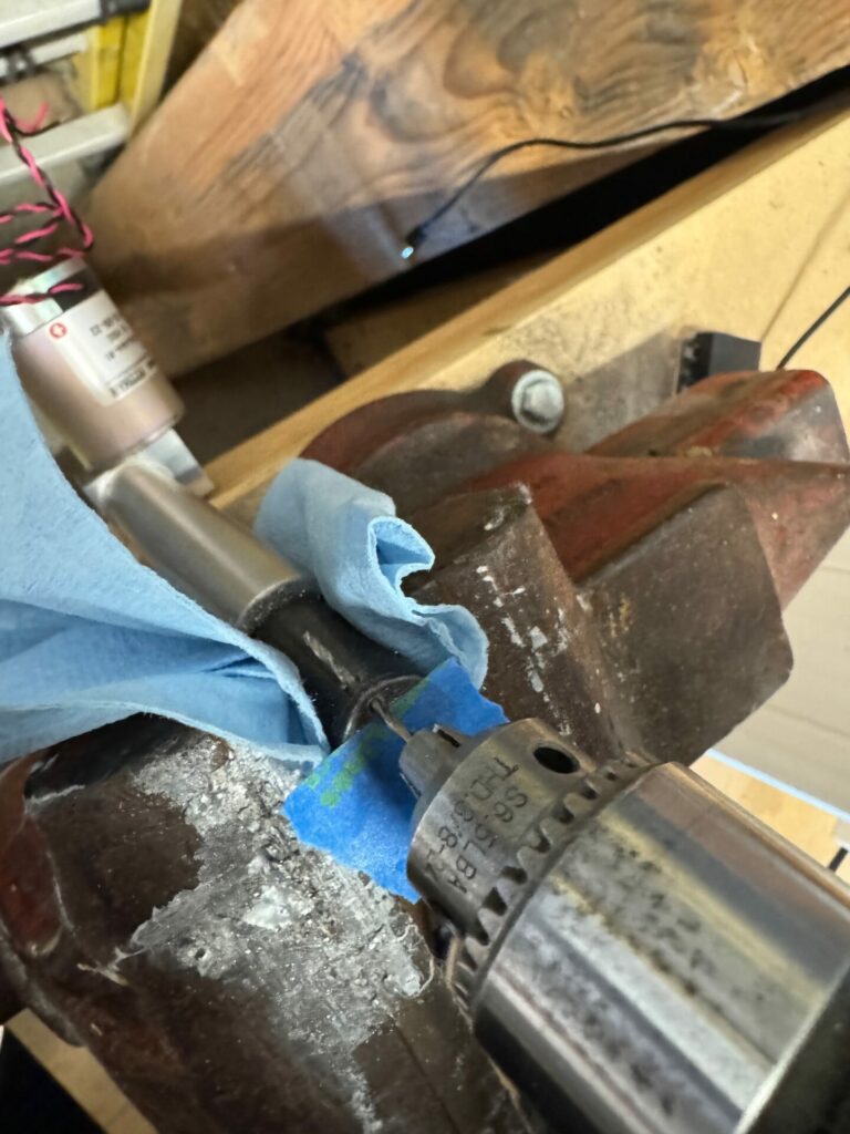
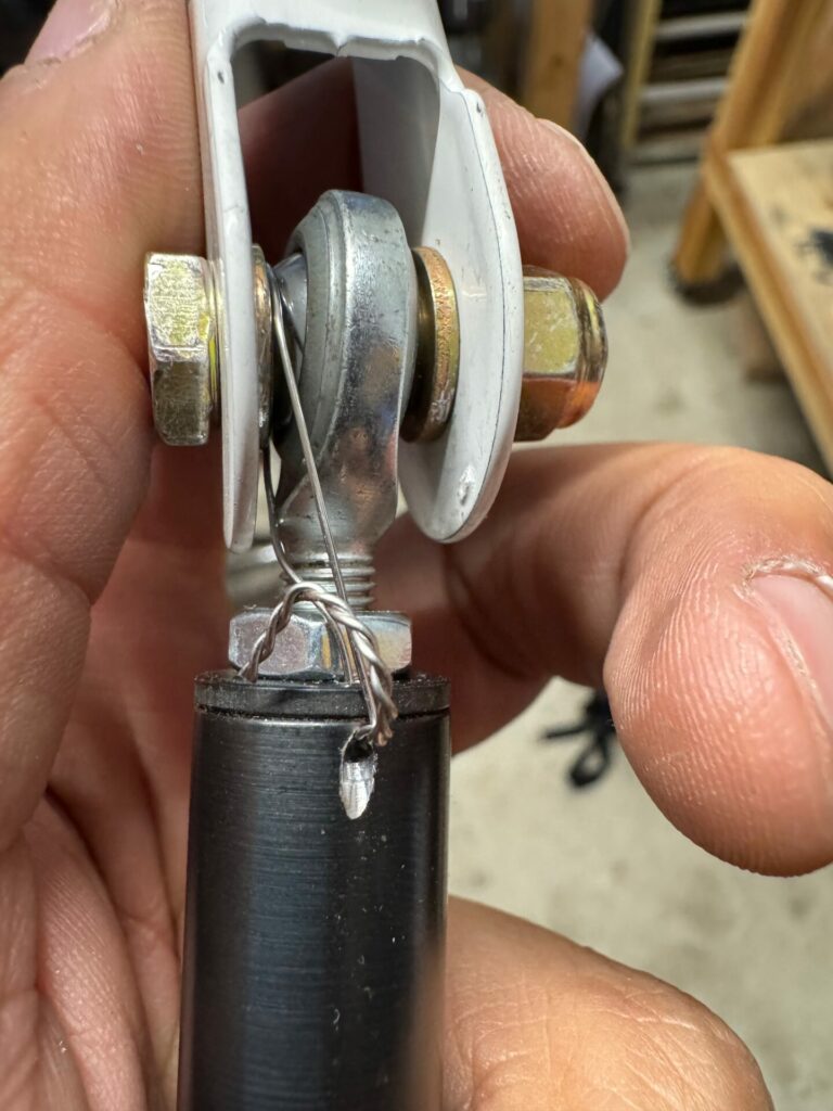
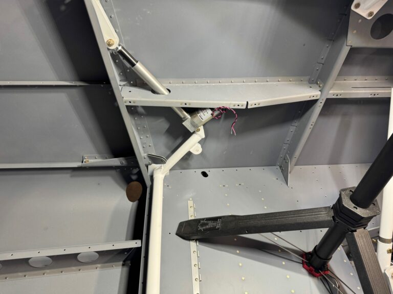
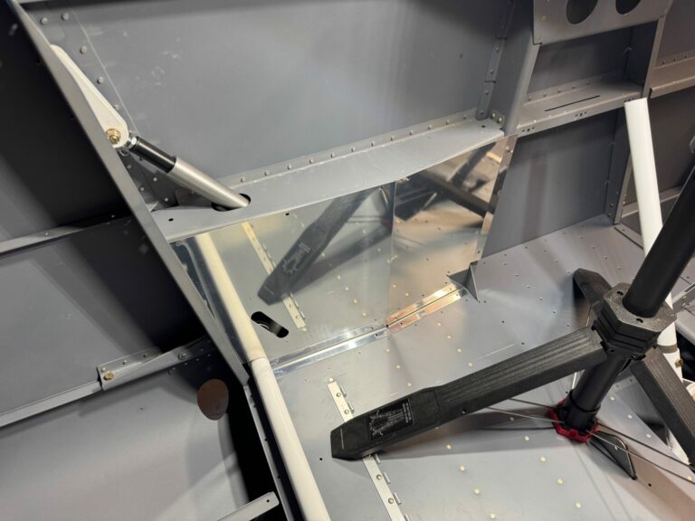
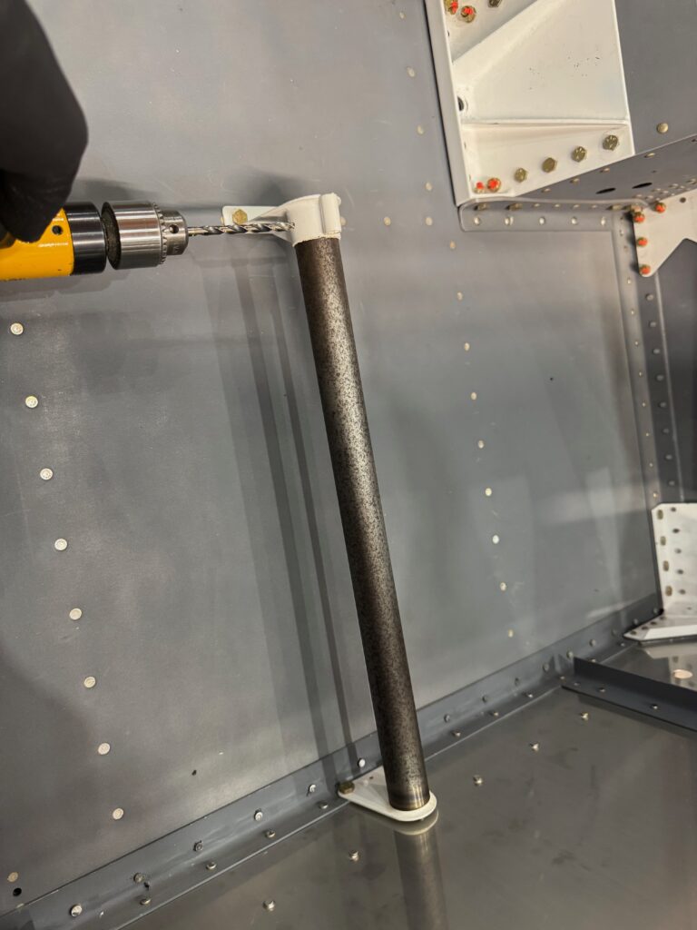
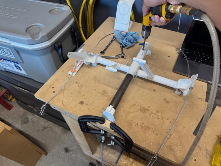
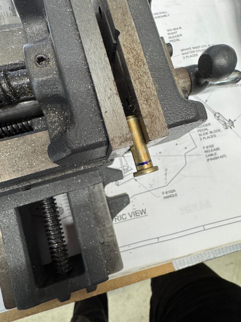
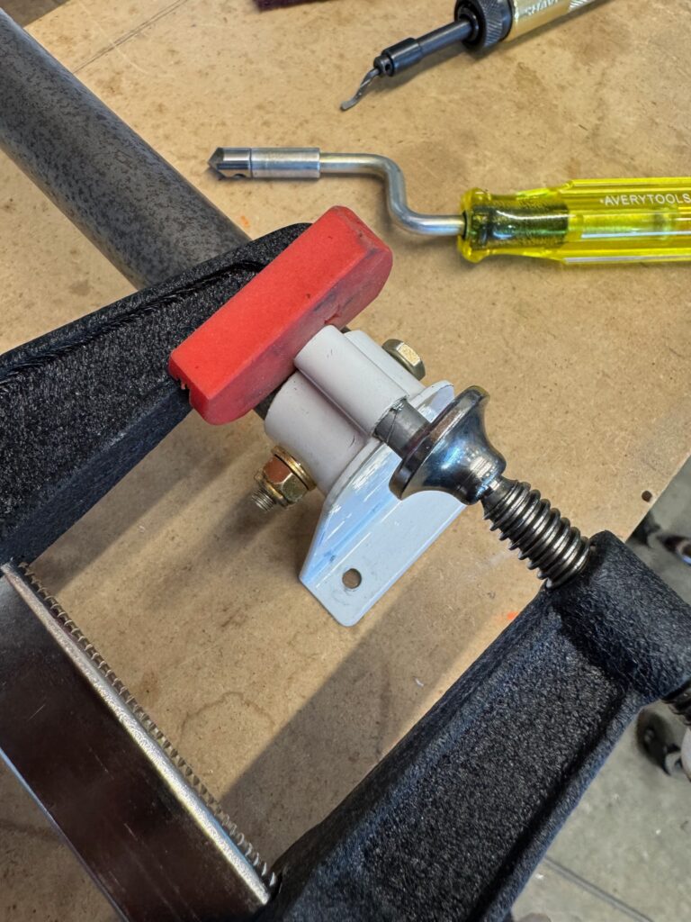
It started with the flap motor install. The only complicated step is drilling the hole for the safety wire. Having the vice to secure the shaft made it easier, but making sure you drill from the right side will guarantee the holes end up in approximately the right place. I found that the best way to get this accurate was to disassemble the head of the rod end.
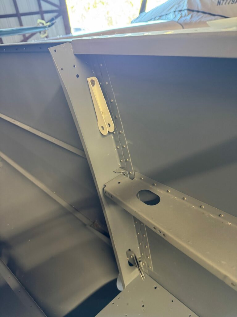
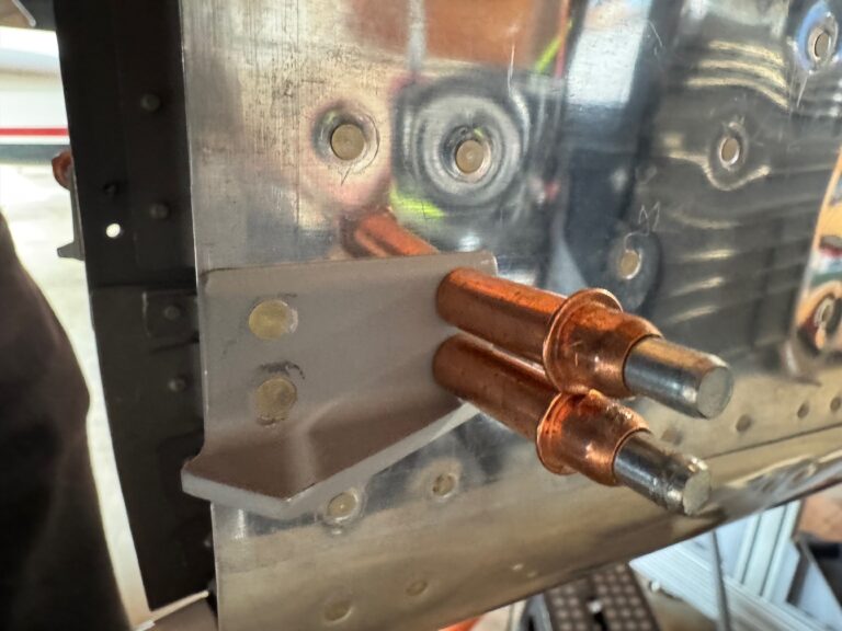
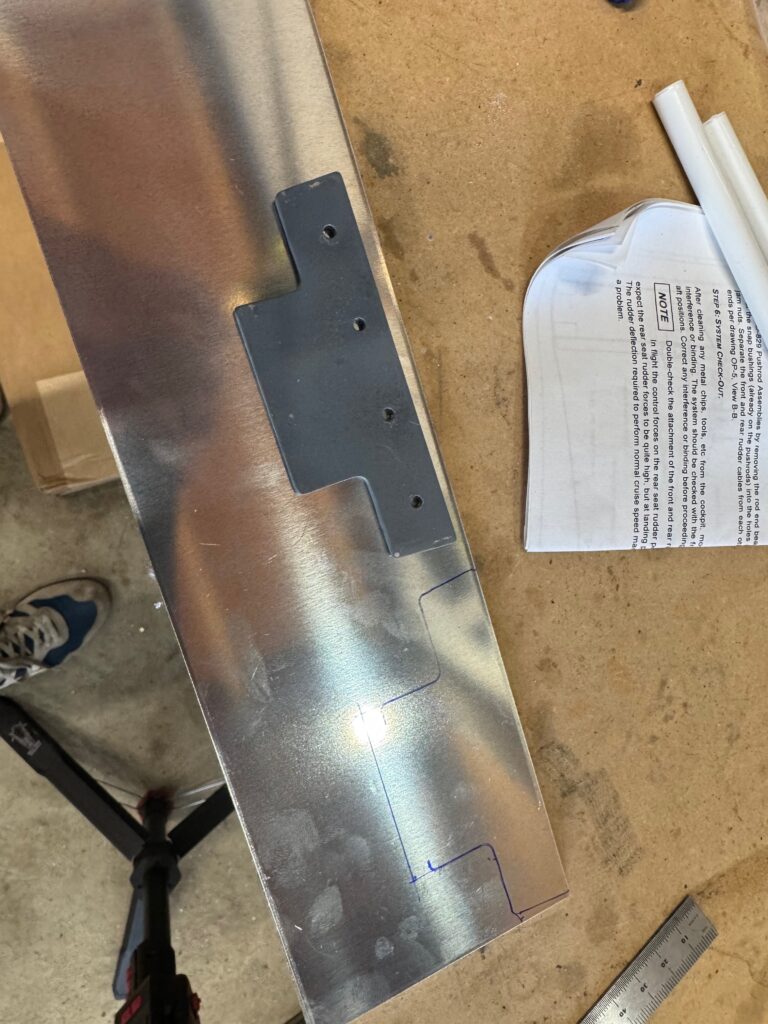
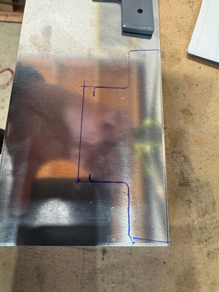
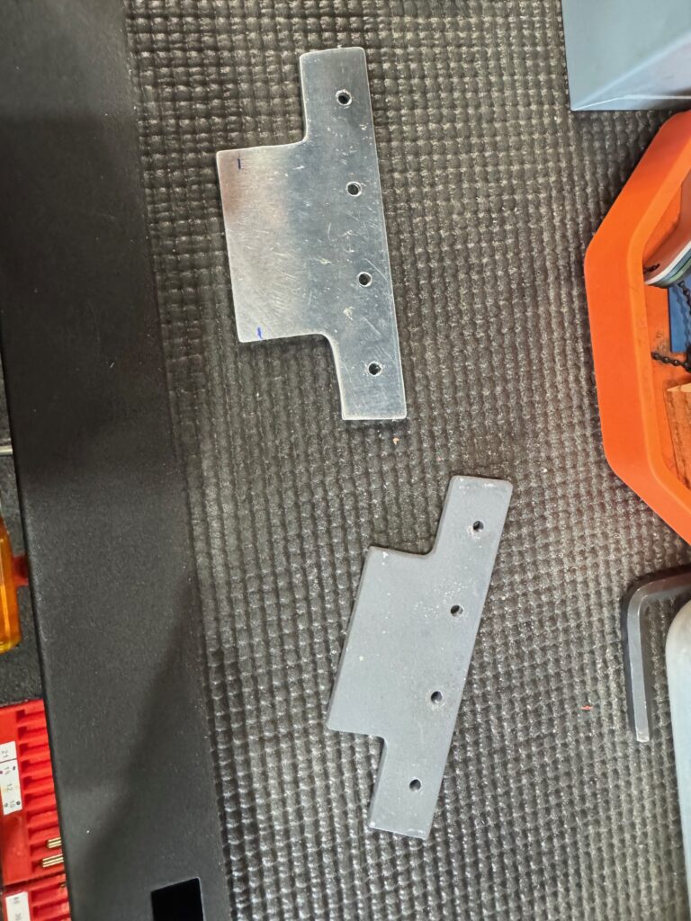
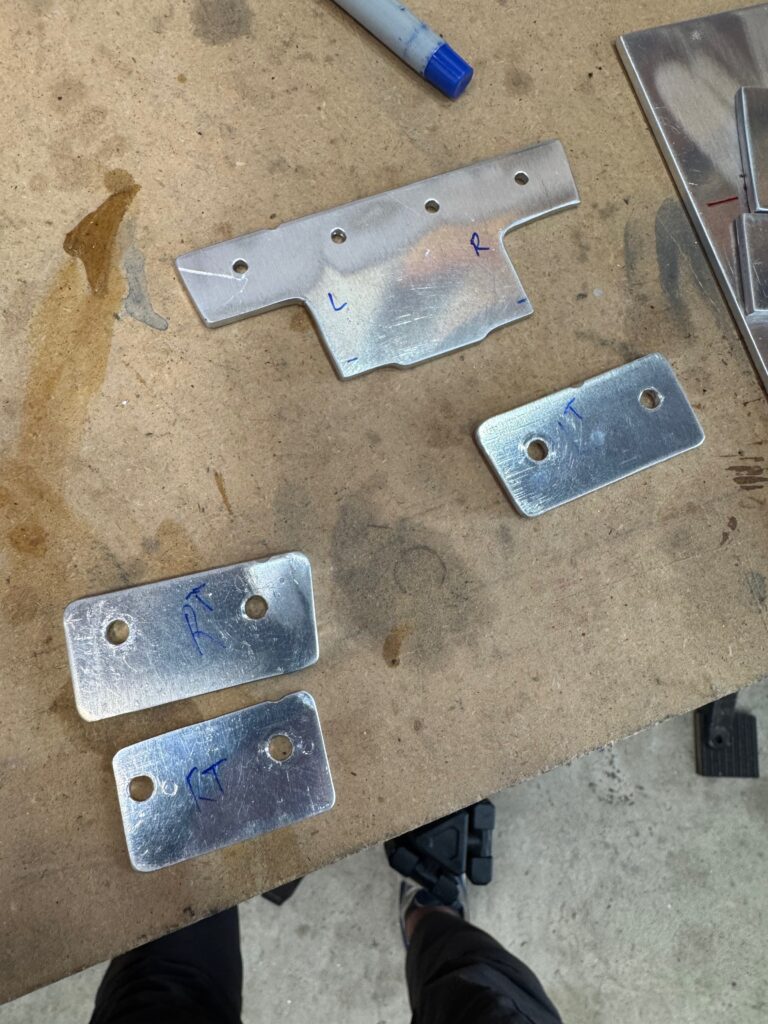
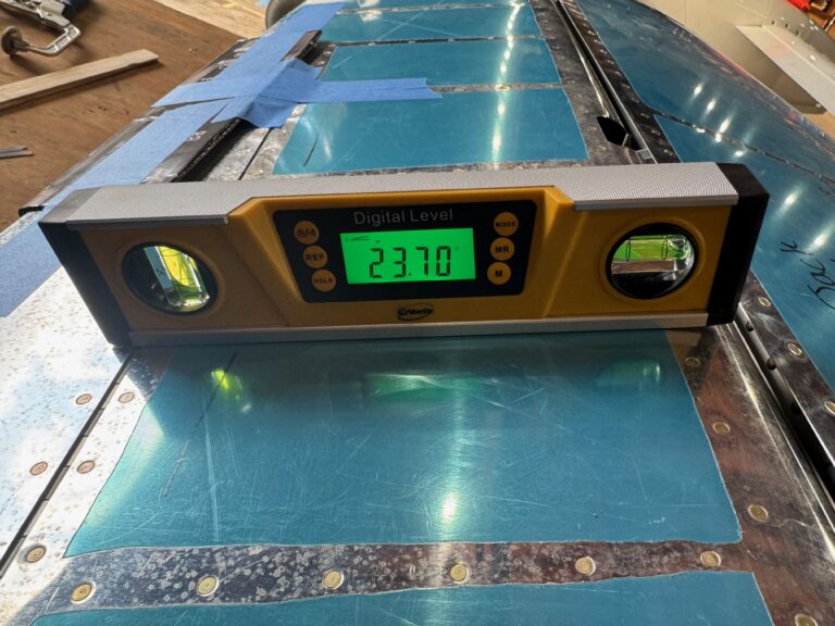
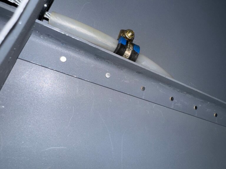
Next I took care of some deferred items. First, Sam came by and helped rivet on the rudder stop. Next, I had deferred trimming the elevator down stop because it was too short to begin with. This is apparently a common issue (i.e. the elevator deflects too far down before trimming any of the stop). I had ordered the stock material a few weeks back, and needed to recreate the stop with a bit more elevator stop material. After a few iterations of trimming I successfully got the deflection to a touch over 23˚ down. Perfect!
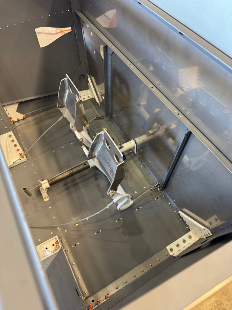
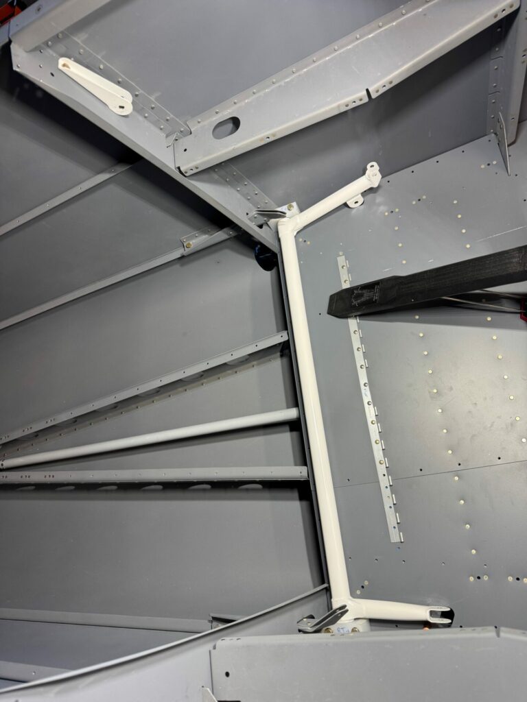
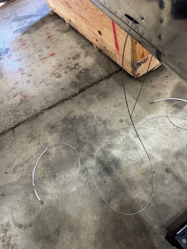
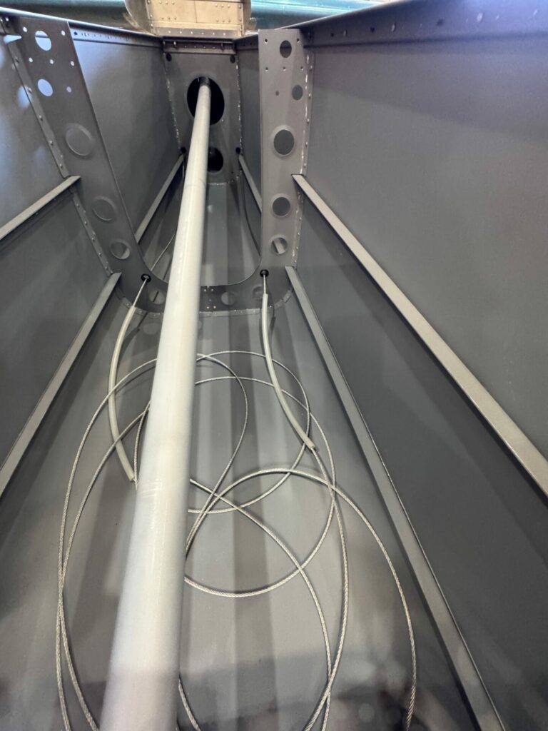
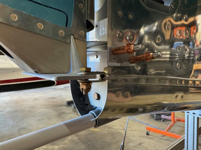
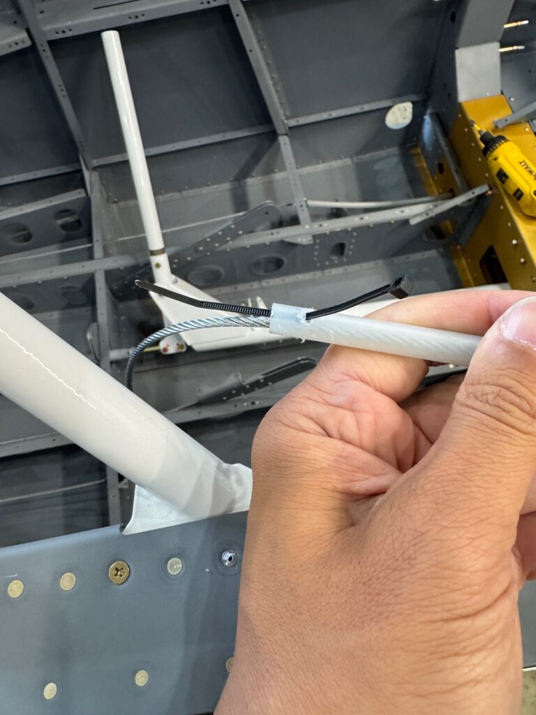
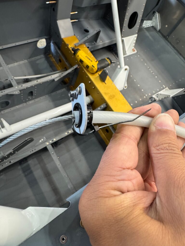
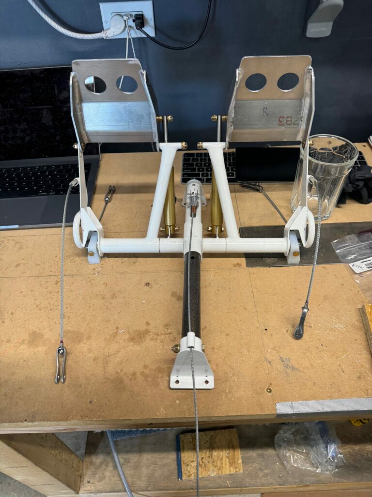
With some of the minor tasks complete, I was excited to get working on the rudder control system. This felt like one of those milestone projects… Rudder Pedals going in?? Can’t wait to deflect the rudder with my feet! There are two major tasks… routing the rudder cables and assembling the rudder pedals. I also will be installing the optional rear rudder pedals. First up was the cables. Nothing too exciting there, but pay attention to the order of steps in the instructions… if not you’ll need to do a lot of re-routing as you discover mis-steps.
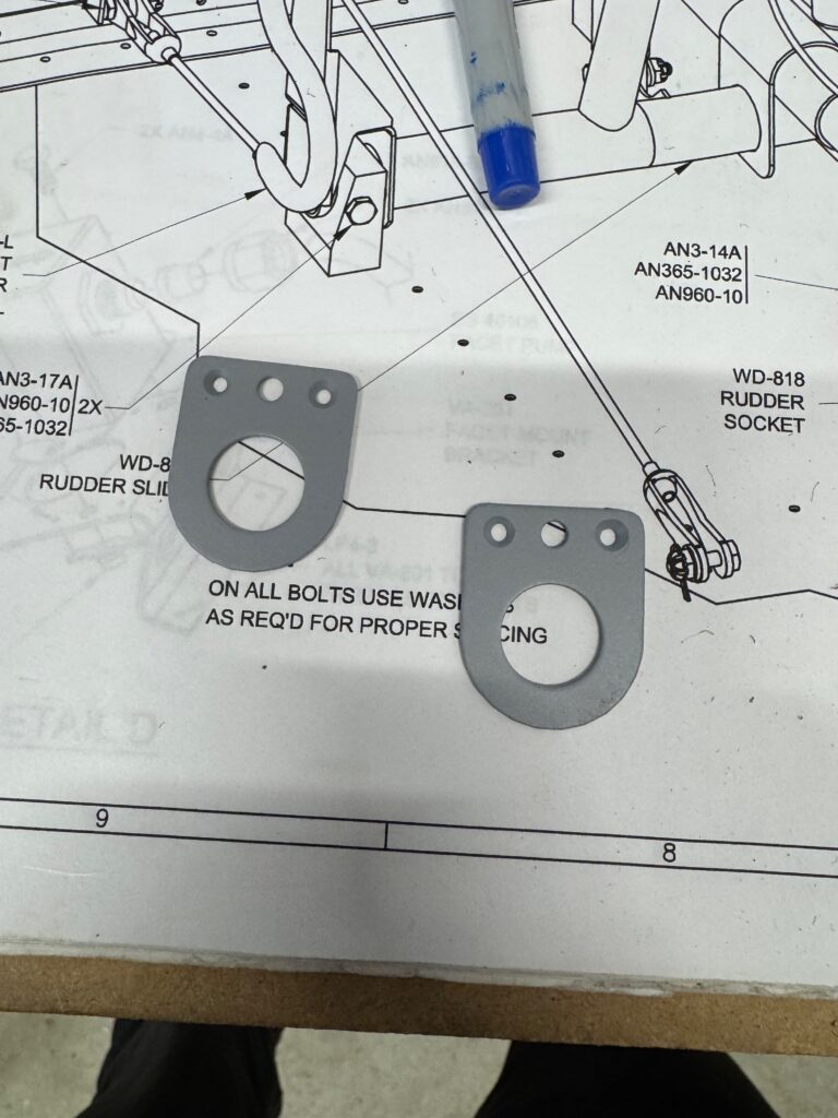
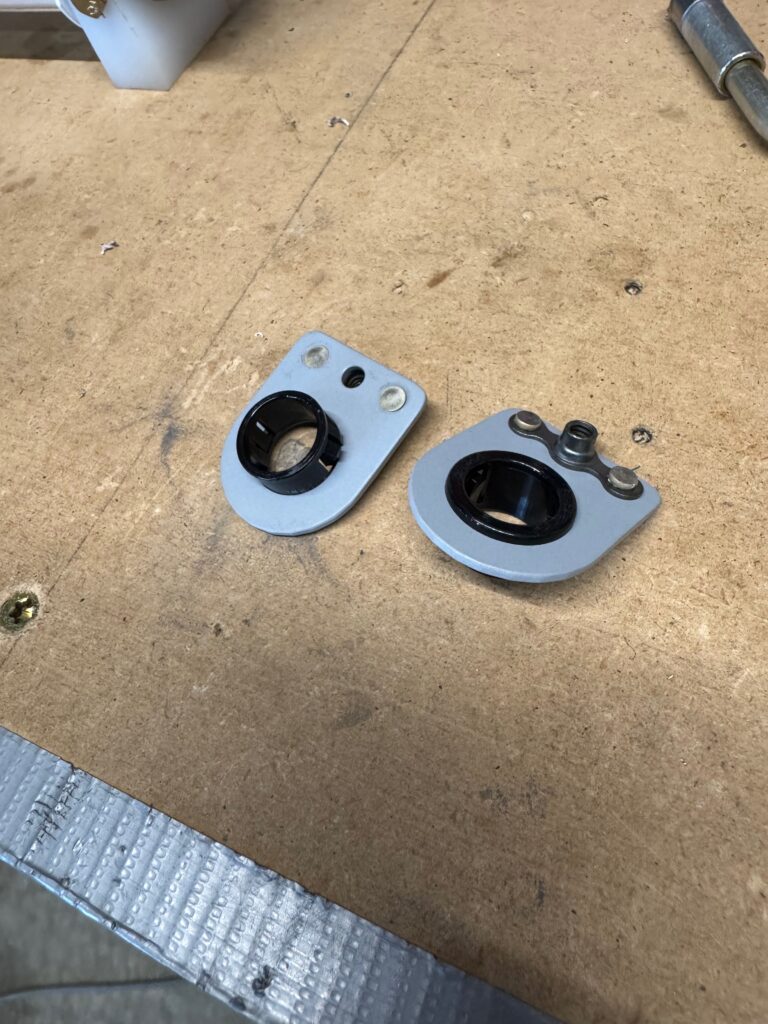
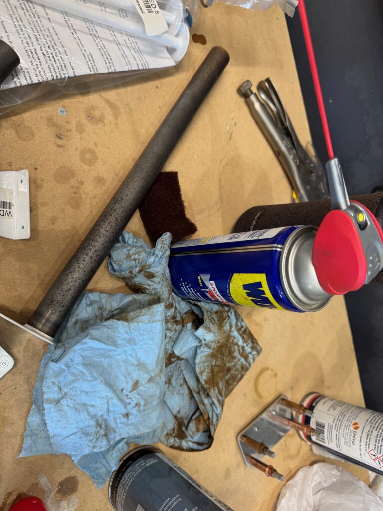
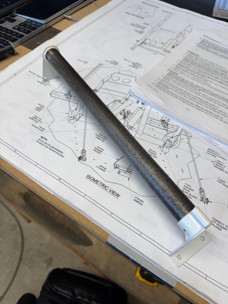
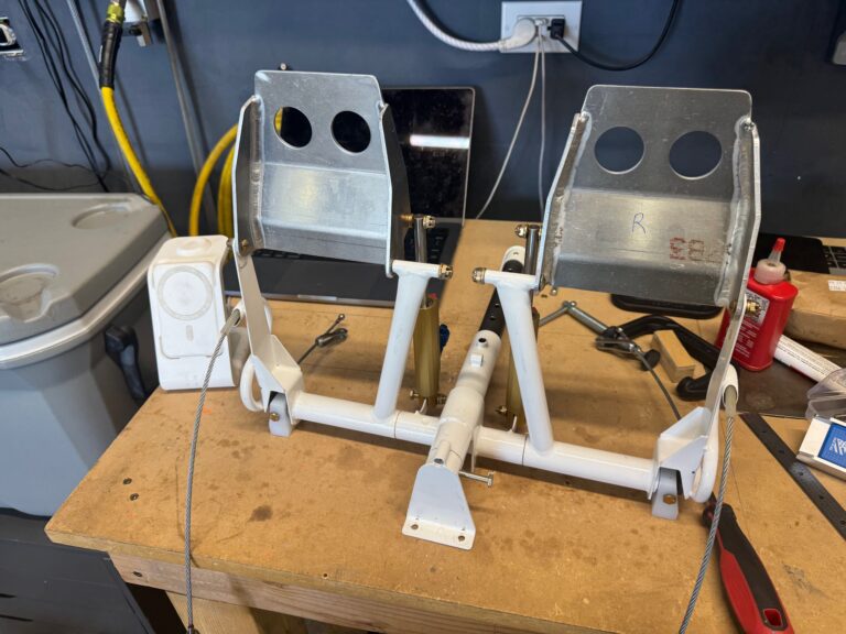
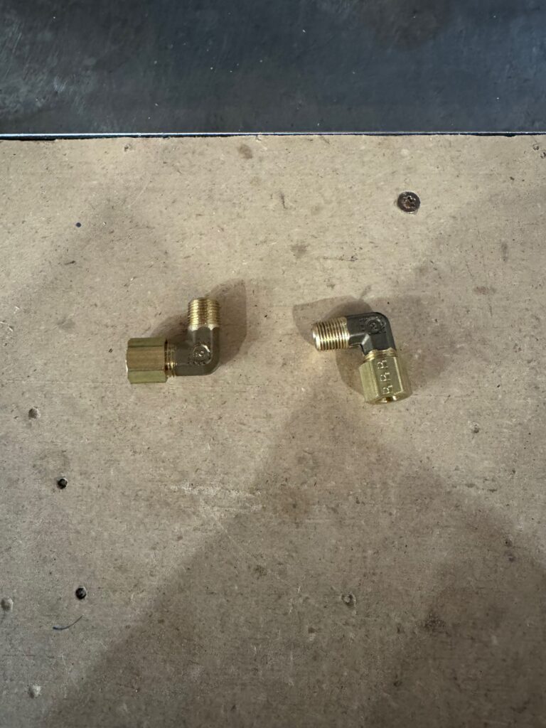
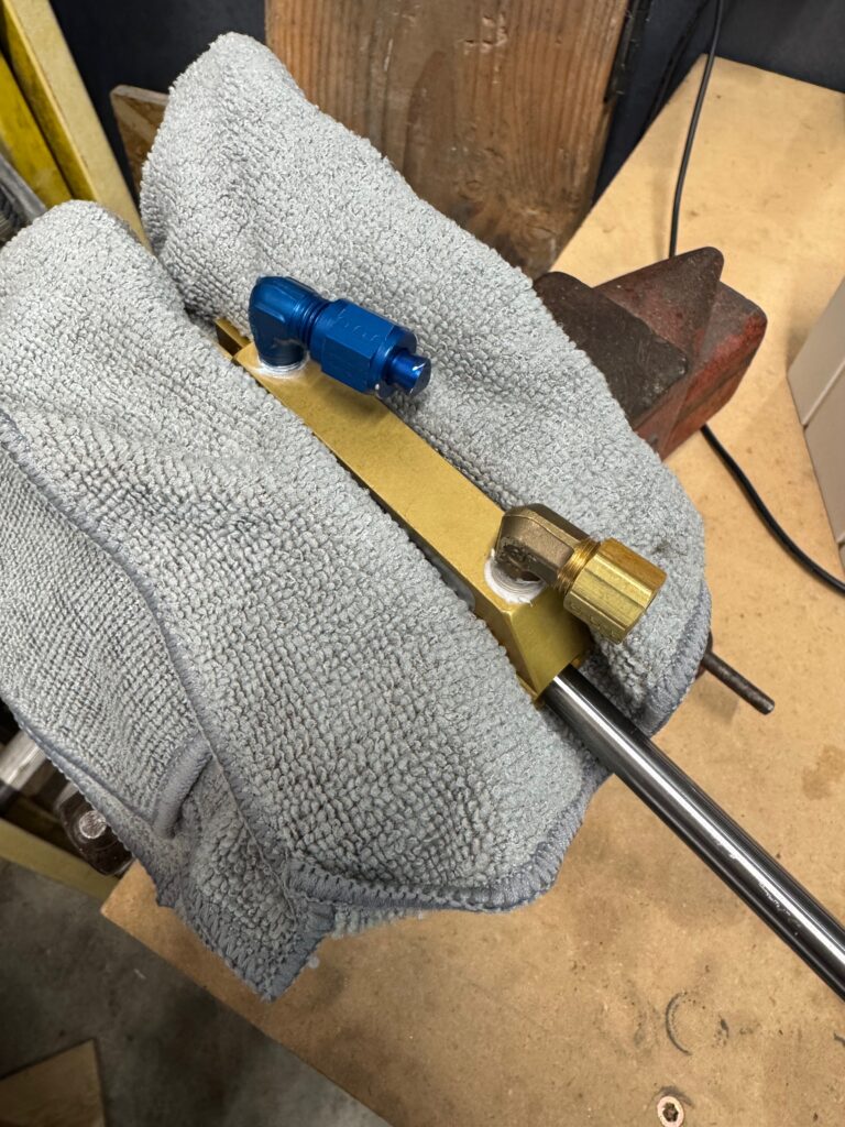
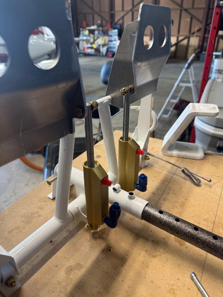
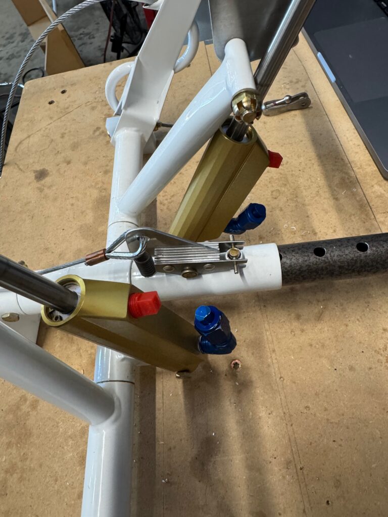
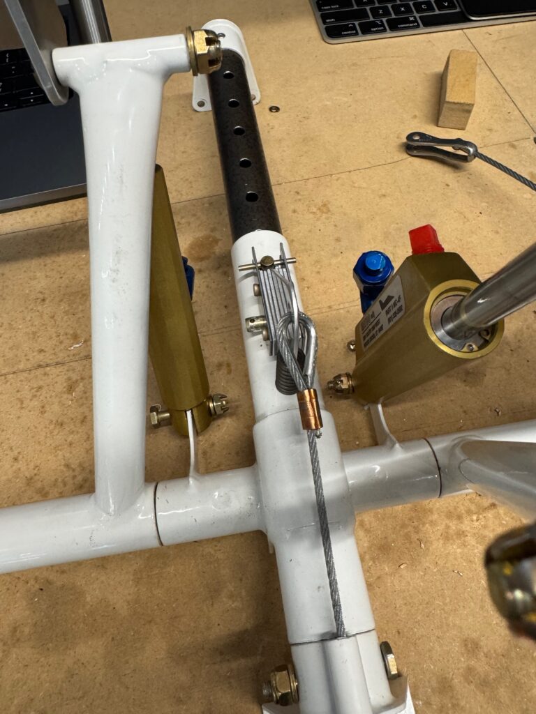
Time for Rudder Pedal Assembly. It is fun to build all this out and deeply understand how it all comes together. It always seems like a mystery, but turns out once you build it yourself, it is a lot more simple than you’d think. After cleaning the surface rust off the parts assembly was straight forward. One surprise was the missing brake line parts that weren’t even on the RV-8 packing slip (F 69-F-04). Make sure you have those parts early! Van’s was nice enough to send them to me for free.
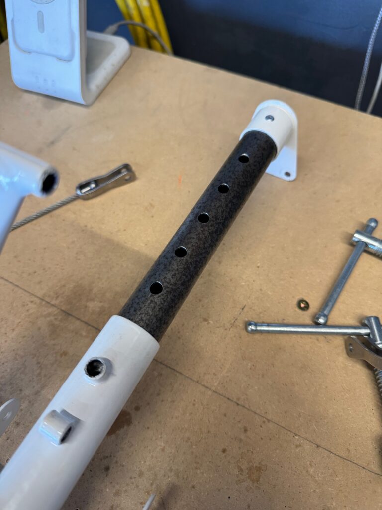
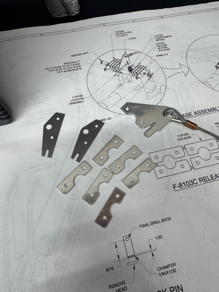
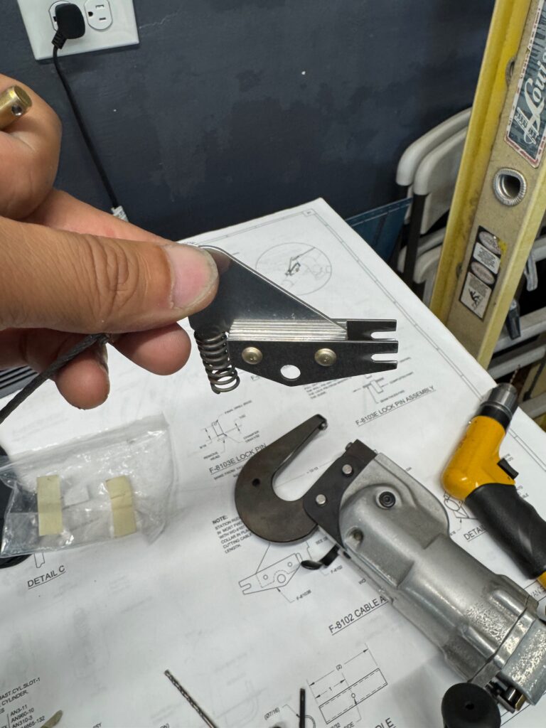
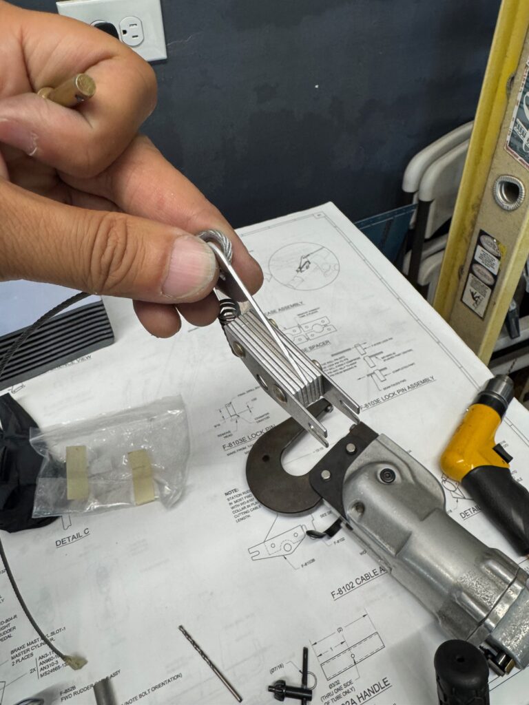
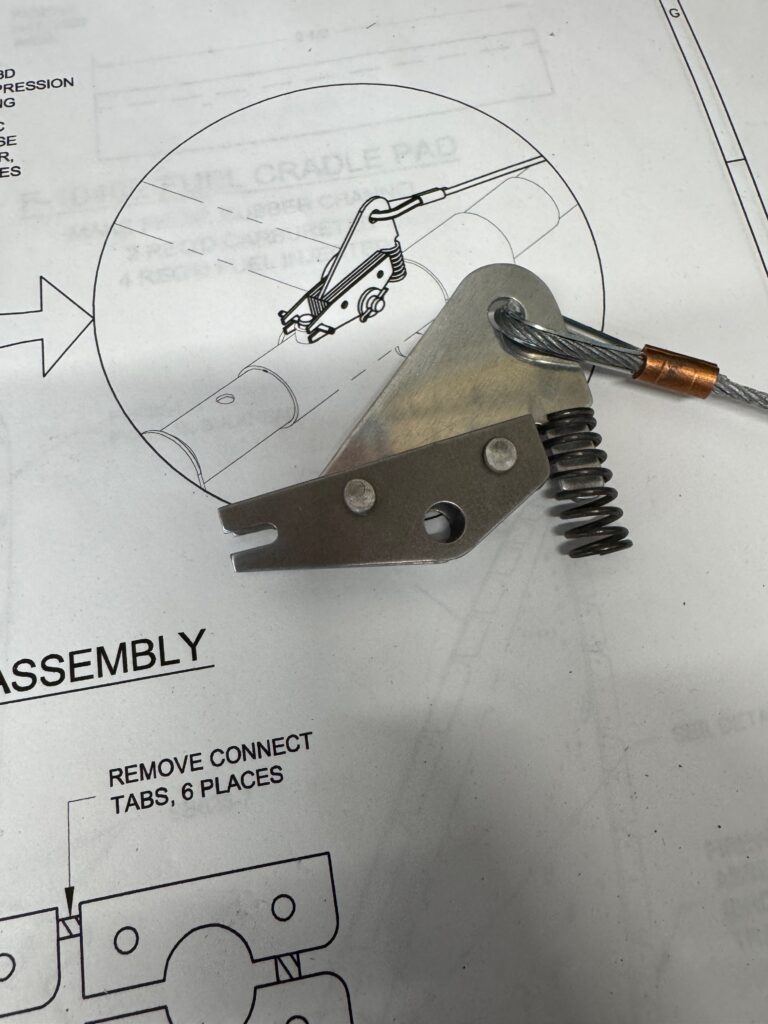
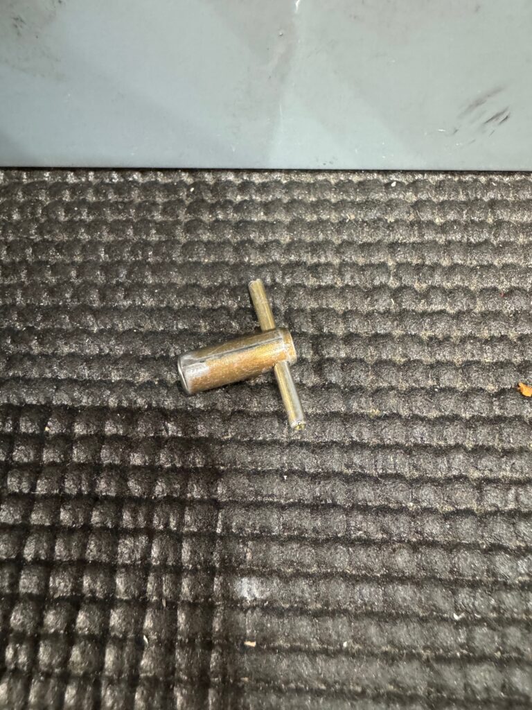
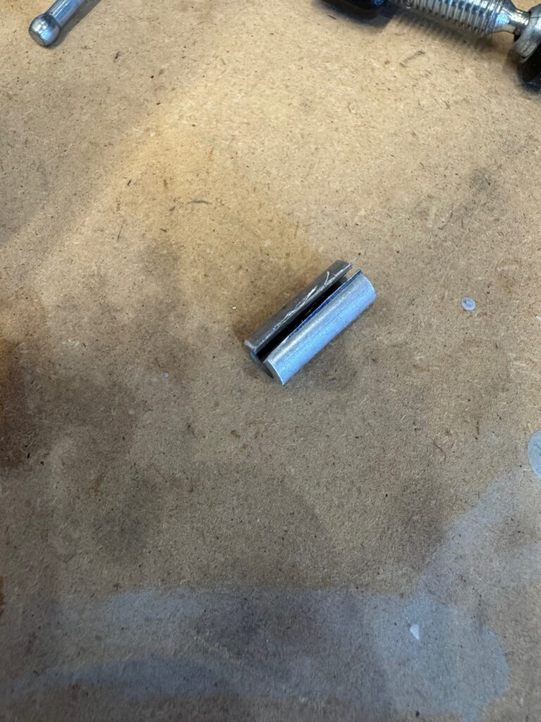
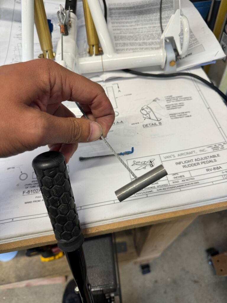
The Release Assembly is a final mechanism to build out. It requires stacking quite a few layers of parts together and fabricating a locking pin. There is a roll pin (MS16562-30) that is supposed to be squeezed through the clevis pin. Although it doesn’t call for it, I found I needed to drill one size up (#41) to get the pin through properly. Another note on this assembly. I found installing the t-handle quite awkward, and the drill sizes in the plans would not work for me. There might be a better solution but I just ended up drilling out the hole a bit larger than plan. Either way, the hitch knot in the cable will not allow it to go through.
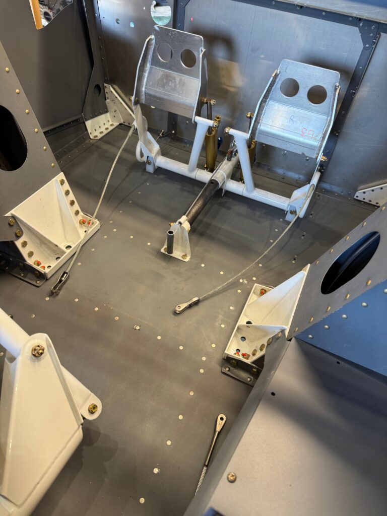
Front Rudder Pedals installed! Big step complete, and one step closer to sitting in the cockpit. Next up will be the rear pedals and then the fuel system! Until then…. Happy Building!
1 comment
You guys are making fantastic progress.Congratulations….
I was highly impressed after yesterday’s visit.