Empennage fitting and drilling continued in the past two sessions. These fitments are pretty key as they are squaring up the stabilizers to the fuselage. In other words, it will have a direct effect on how the plane flies. Once you drill, you get what you get, and there’s not really any going back. So definitely a measure thrice, drill once…. hopefully. This post will mostly be a narrative of photos, but definitely pay attention to the ways I squared up the various axes. They are all based on plans recommendations, but pictures are worth a thousand words. I definitely had to do a lot of imagining to figure out how to get certain things done.
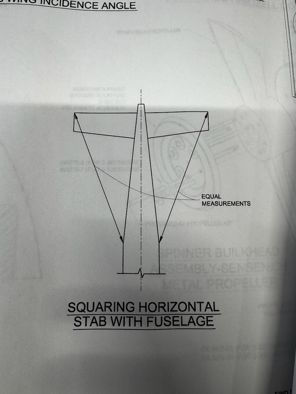
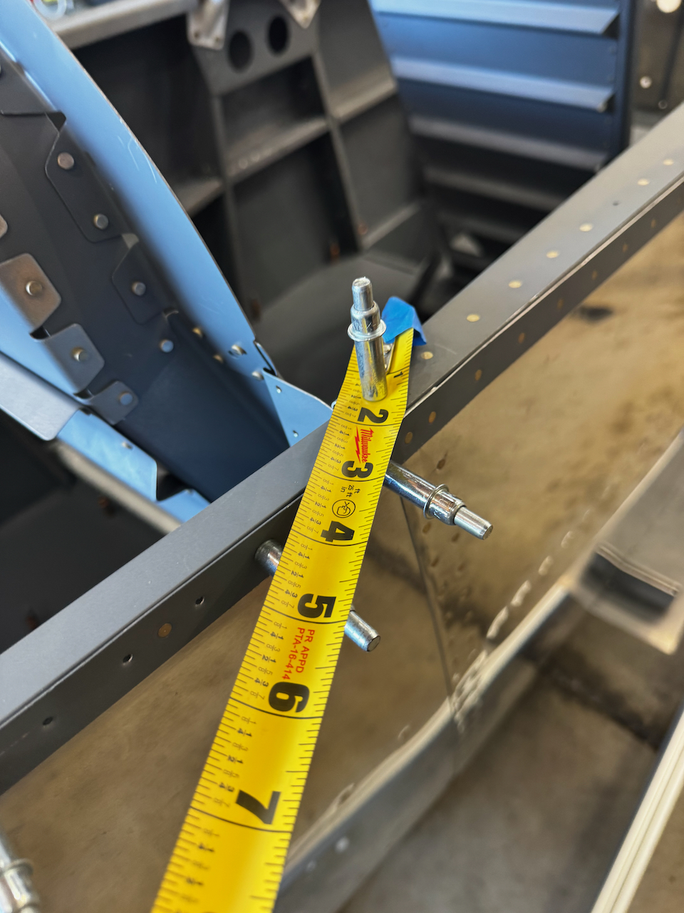
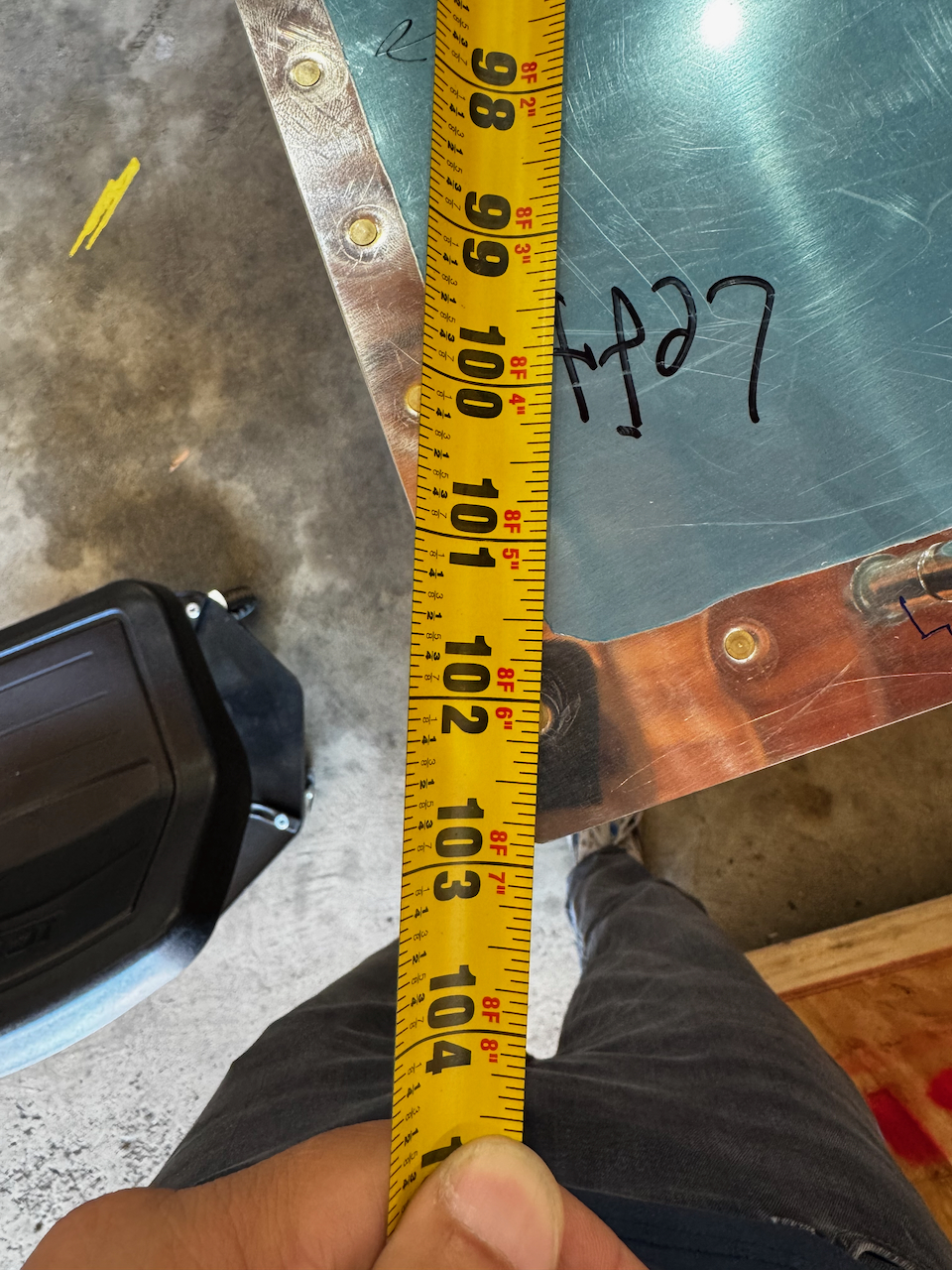
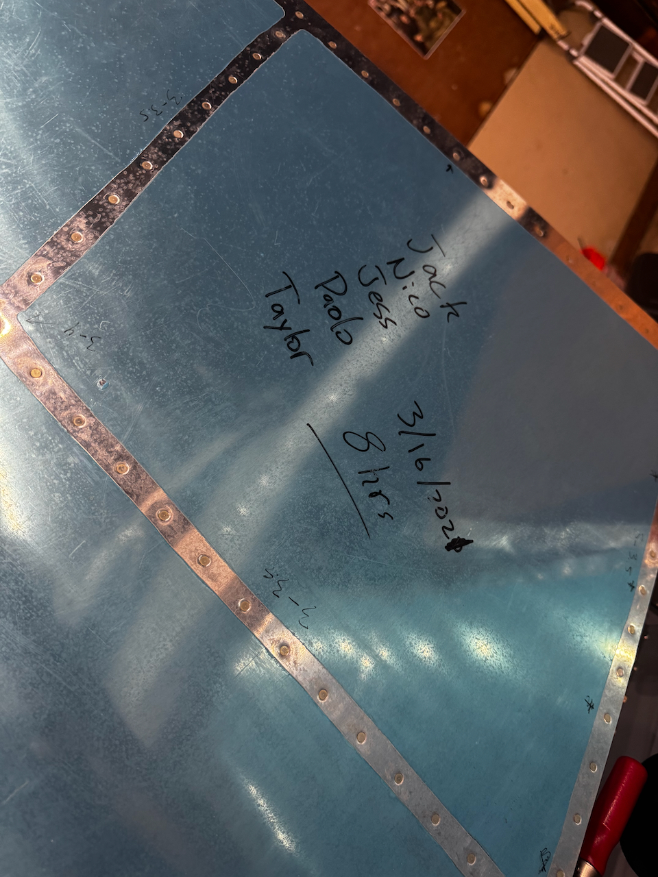
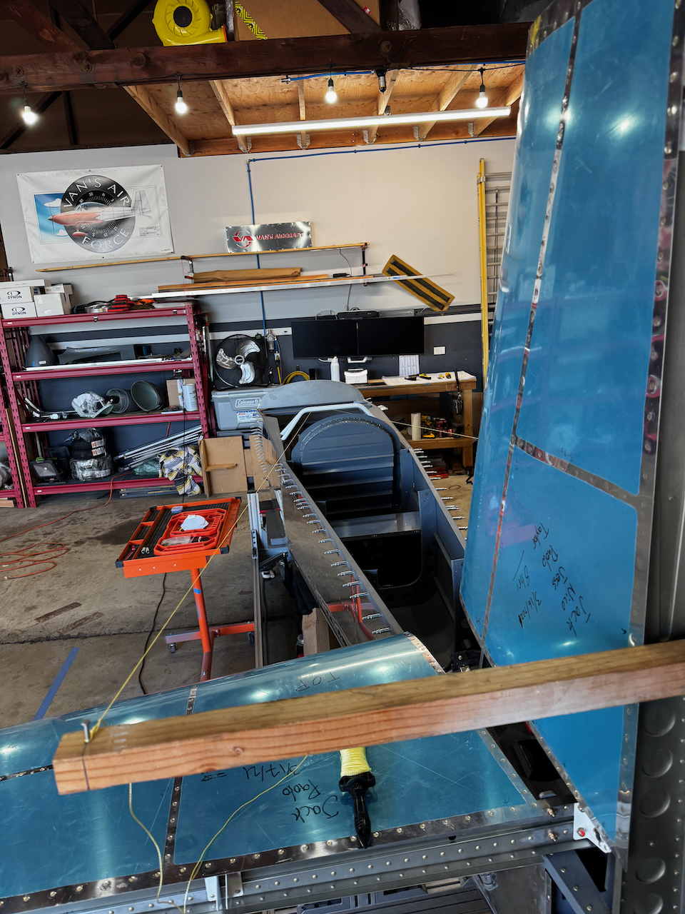
It started with the horizontal stabilizer. I had already leveled it laterally, but now it was time to square it up so that the tips were equivalent distances from a reference point along the fuselage side skins. The unqiue epiphany was that my measuring tape had the perfect hole to put a silver cleco through… so by selecting a rivet hole that existed on both sides at the same logitudinal location, I could reliably measure the distances fairly easily. After many many verifications, I drilled the holes, effectively locking in final location of the horizontal stabilizer for good! Whew!!
The basic gist of how to measure square
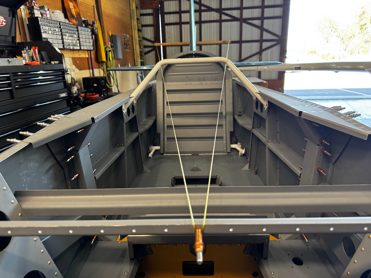
I used existing pre-drilled rivet holes after of the rear seat to secure my measuring tape. That hole was convenient!
I was able to get the two tips to be within 1/32″ of each other
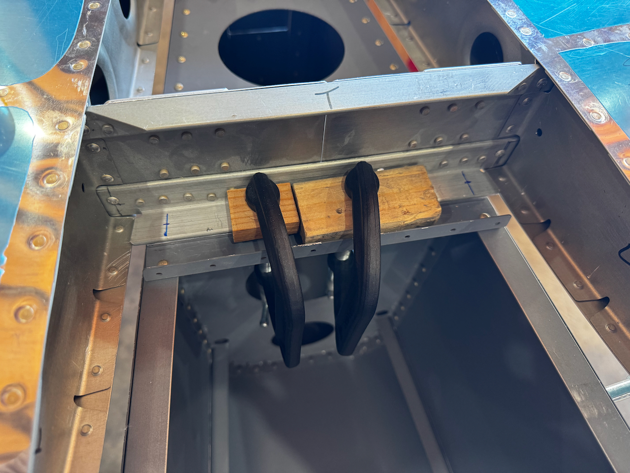
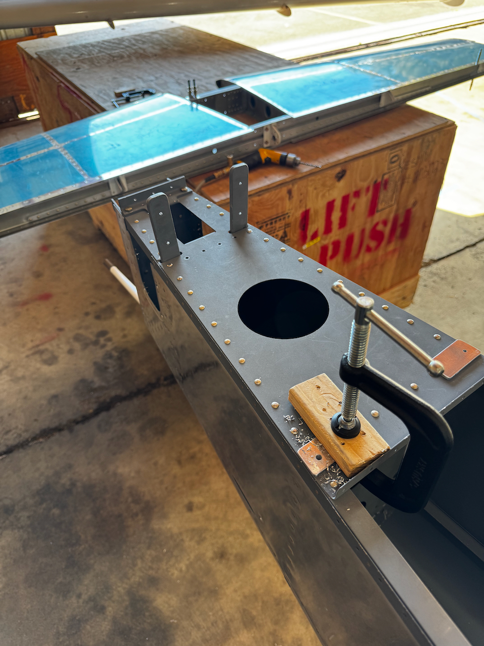
once square, I clamped down hard before drilling the marked outboard holes (as marked per plans). I was able to drill the initial #30 hole, but expanding to the #12 required taking apart the stabilizer.
Clamping everything down nicely ensured that the enlargened holes had the best chance of lining up.
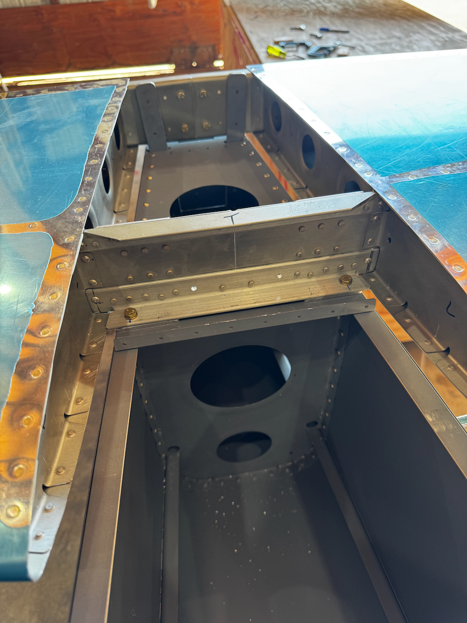
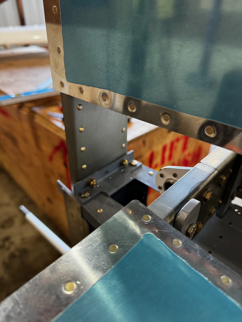
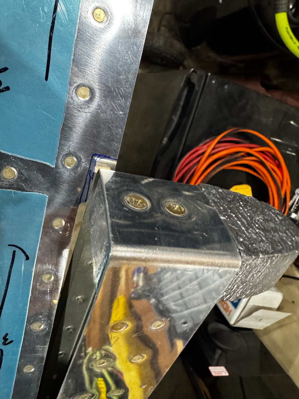
The closer spacer was a touch more challenging since there were two spacers required to get the stabilizer level.
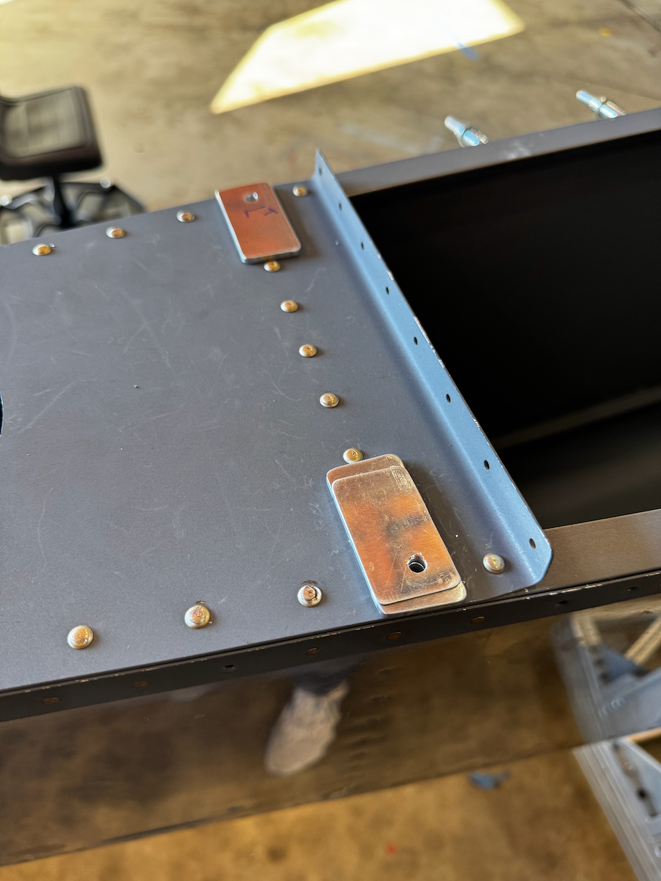
First final sized holes aligned well!
And thank goodness, so did the second!
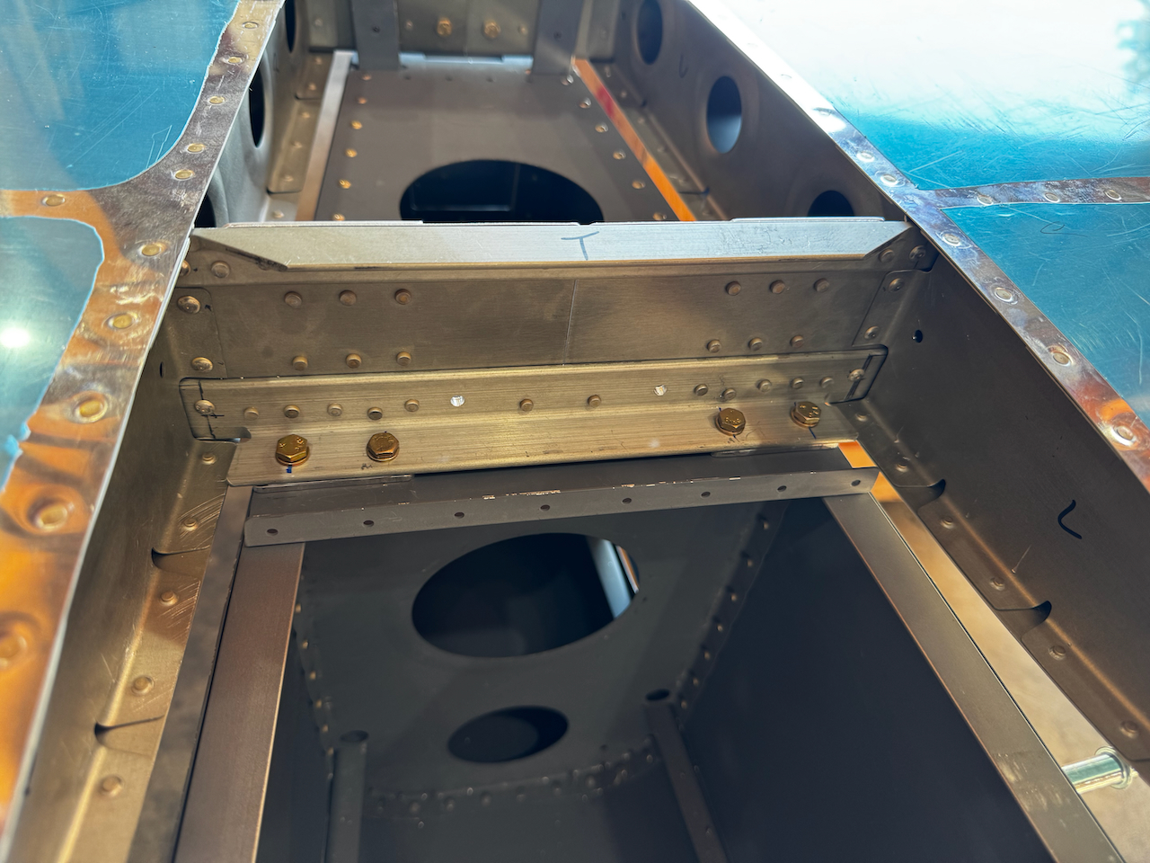
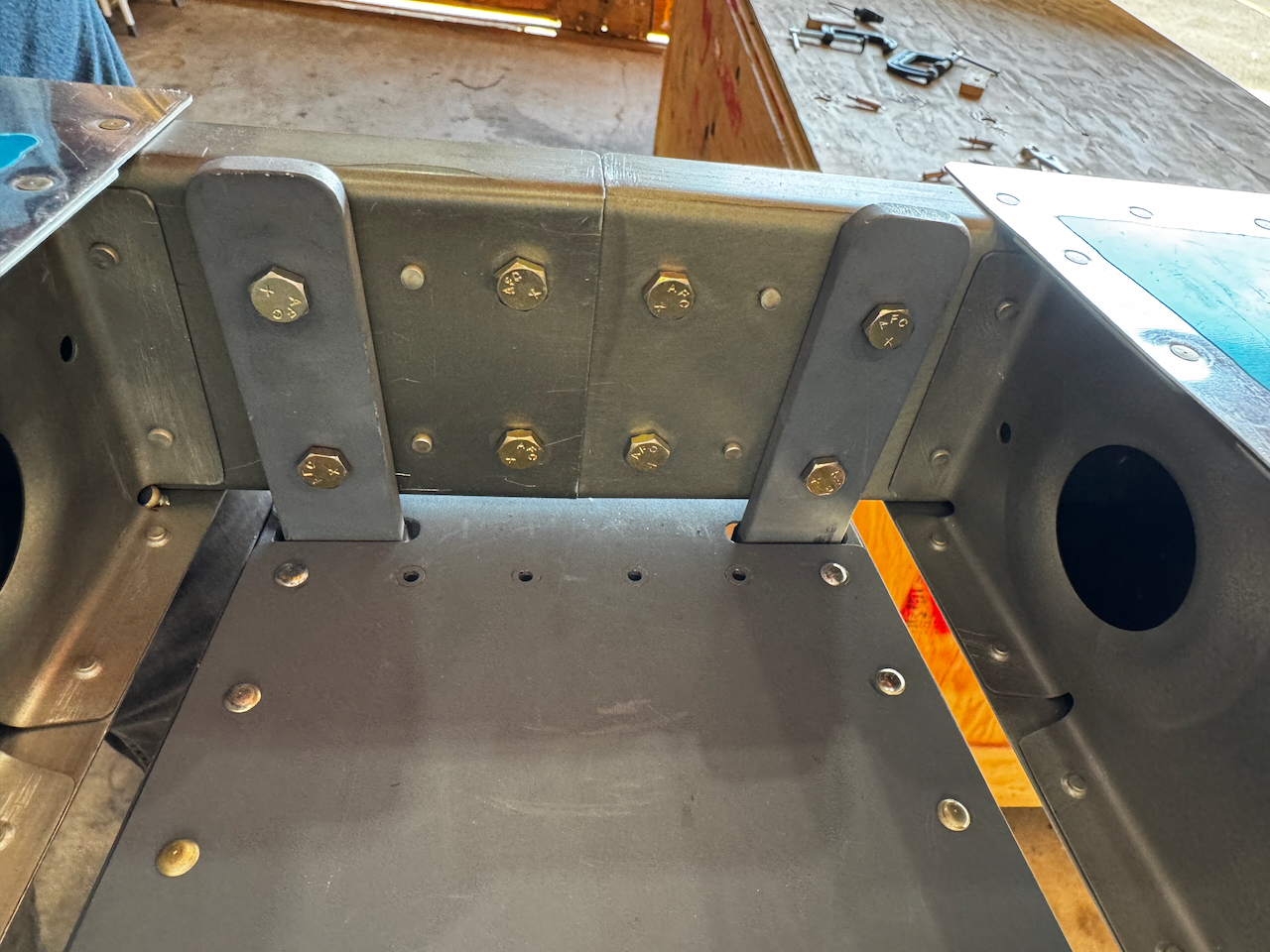
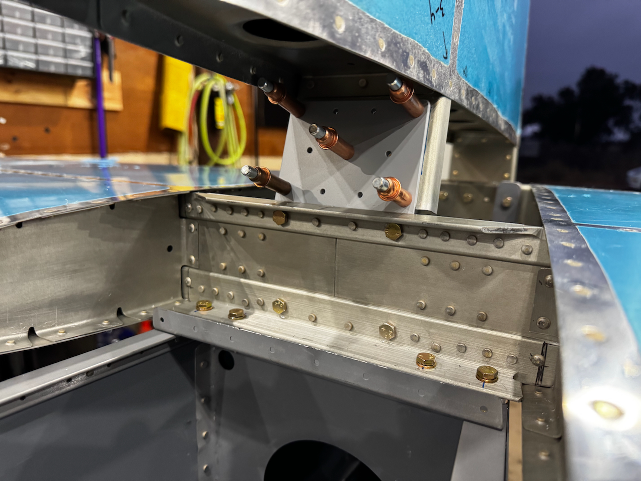
With the forward bolts installed, I final size drilled #12 the stab bars, and put in the bolts.
looks great from the back as well!!
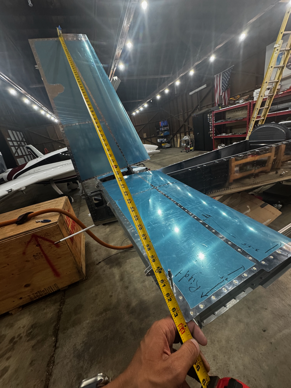
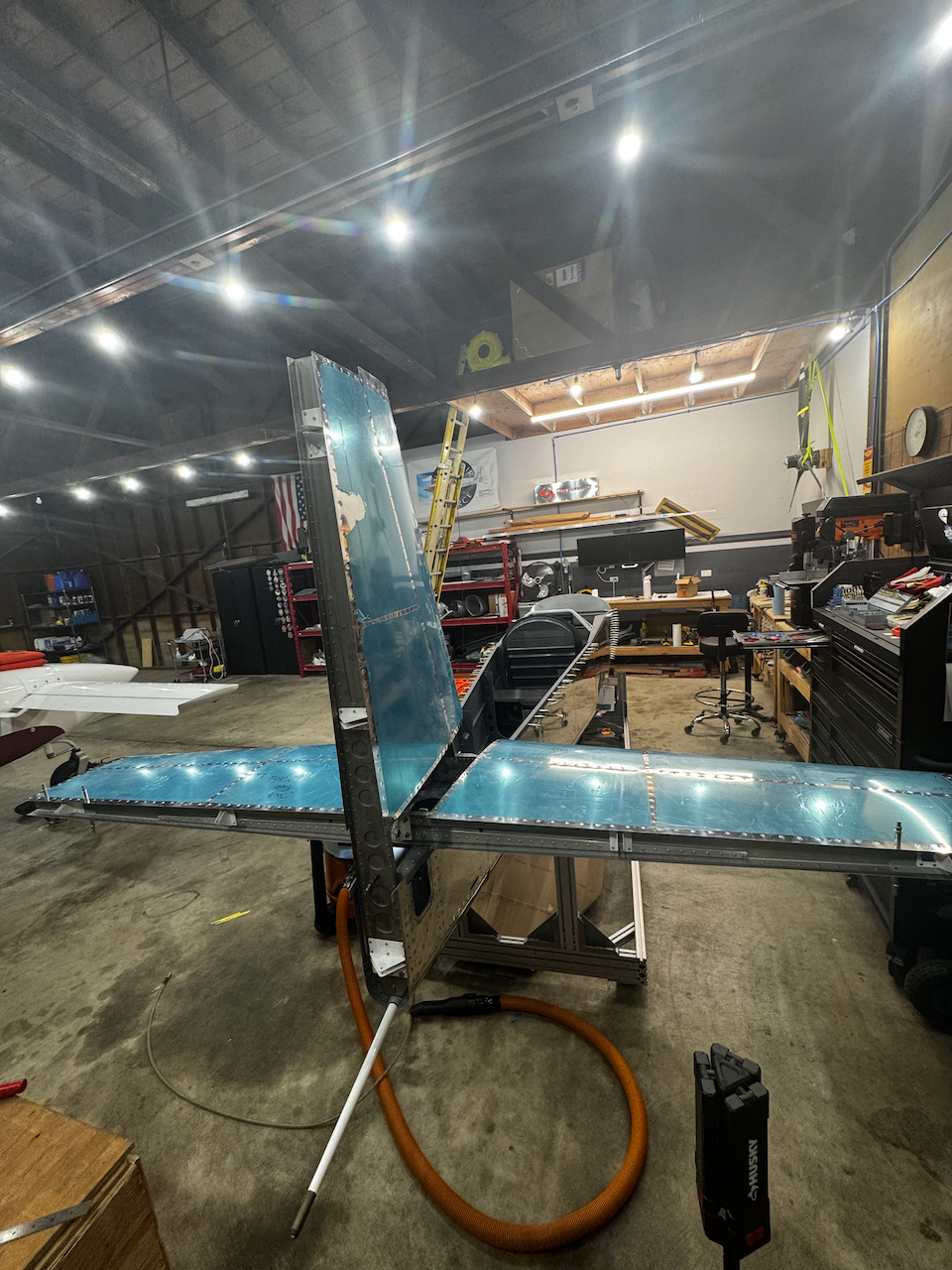
Next up was the rudder. I was excited to see the full stabilizer install. It was REALLY going to start looking more like a plane than a canoe after that! I used the similar technique for vertically squaring the rudder using available rivet holes to attach my tape measures, the slowly tweaking back and forth and re-measuring until the two sides where equivalent. The challenge on this step was ensuring edge distance for both double plates. In the end I was just barely in tolerances, and not sure how I could get it much better. Time to Drill!
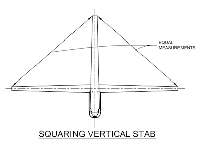
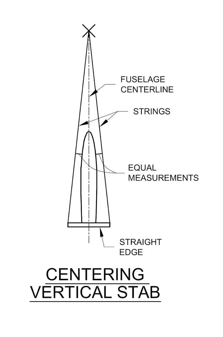
Plan for squaring vertical stab
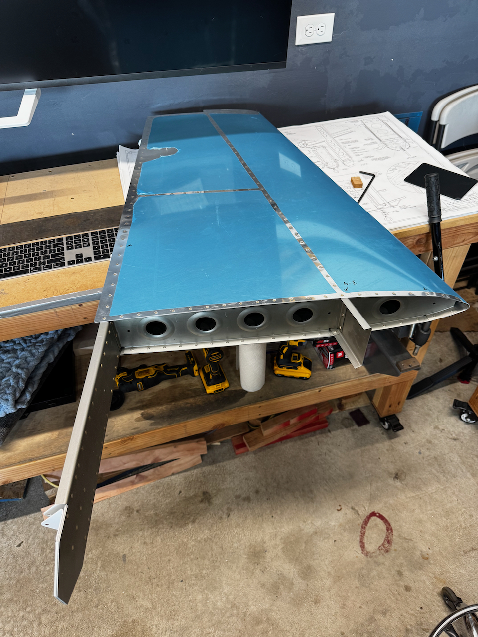
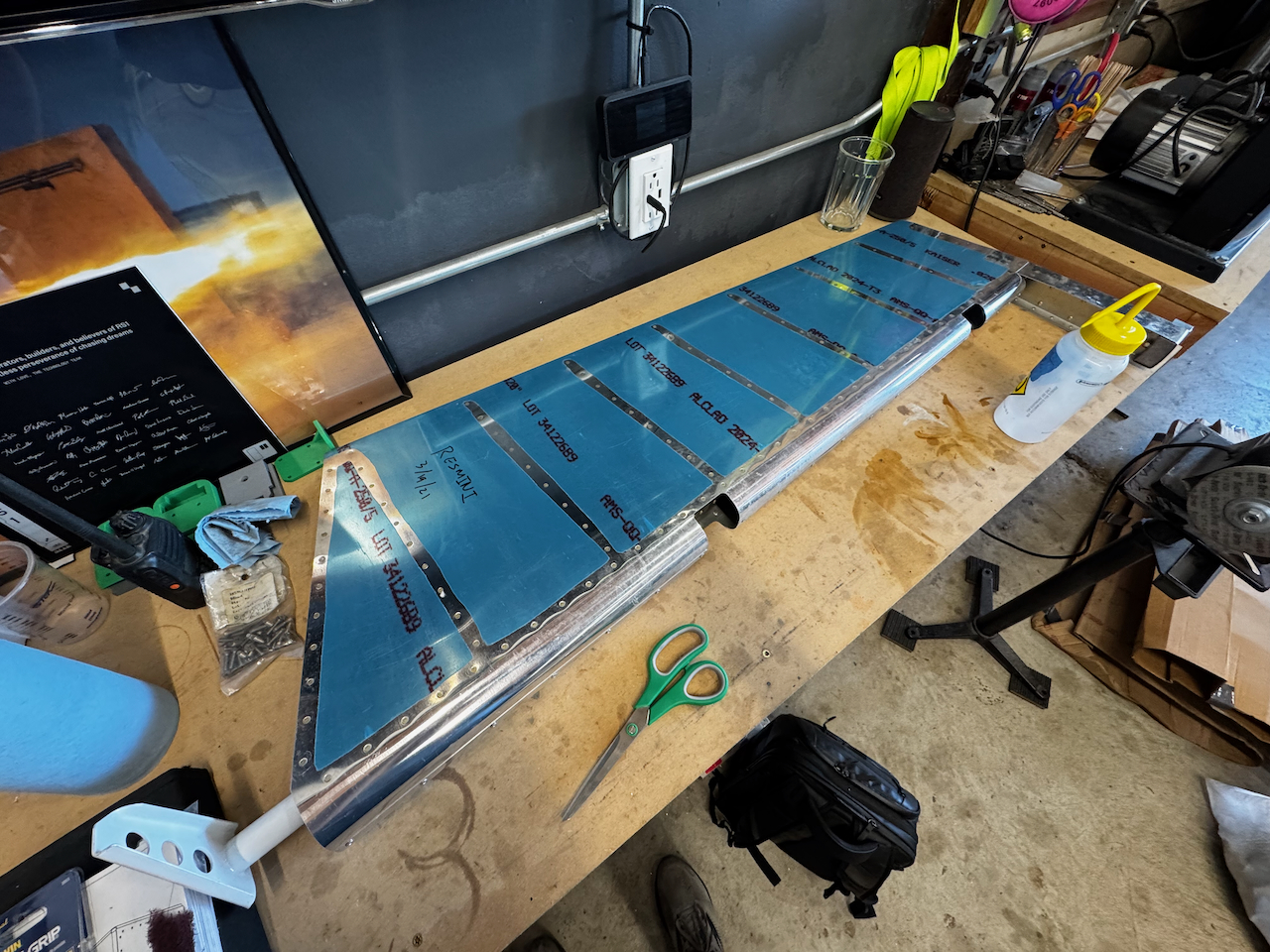
Rudder Time!
Another sub-assembly that has been patiently waiting.
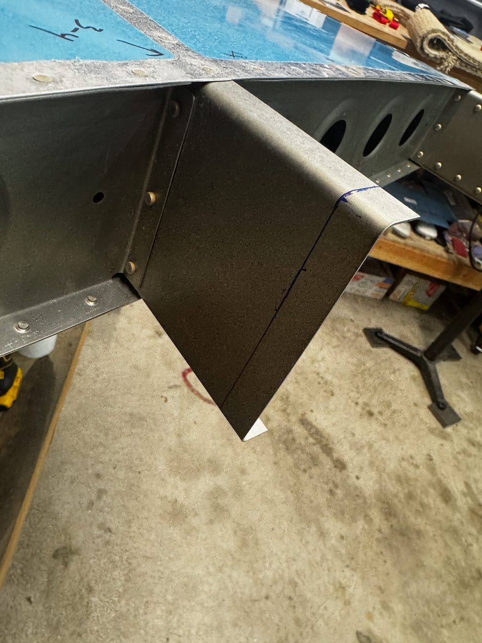
marked for trimming as per plans
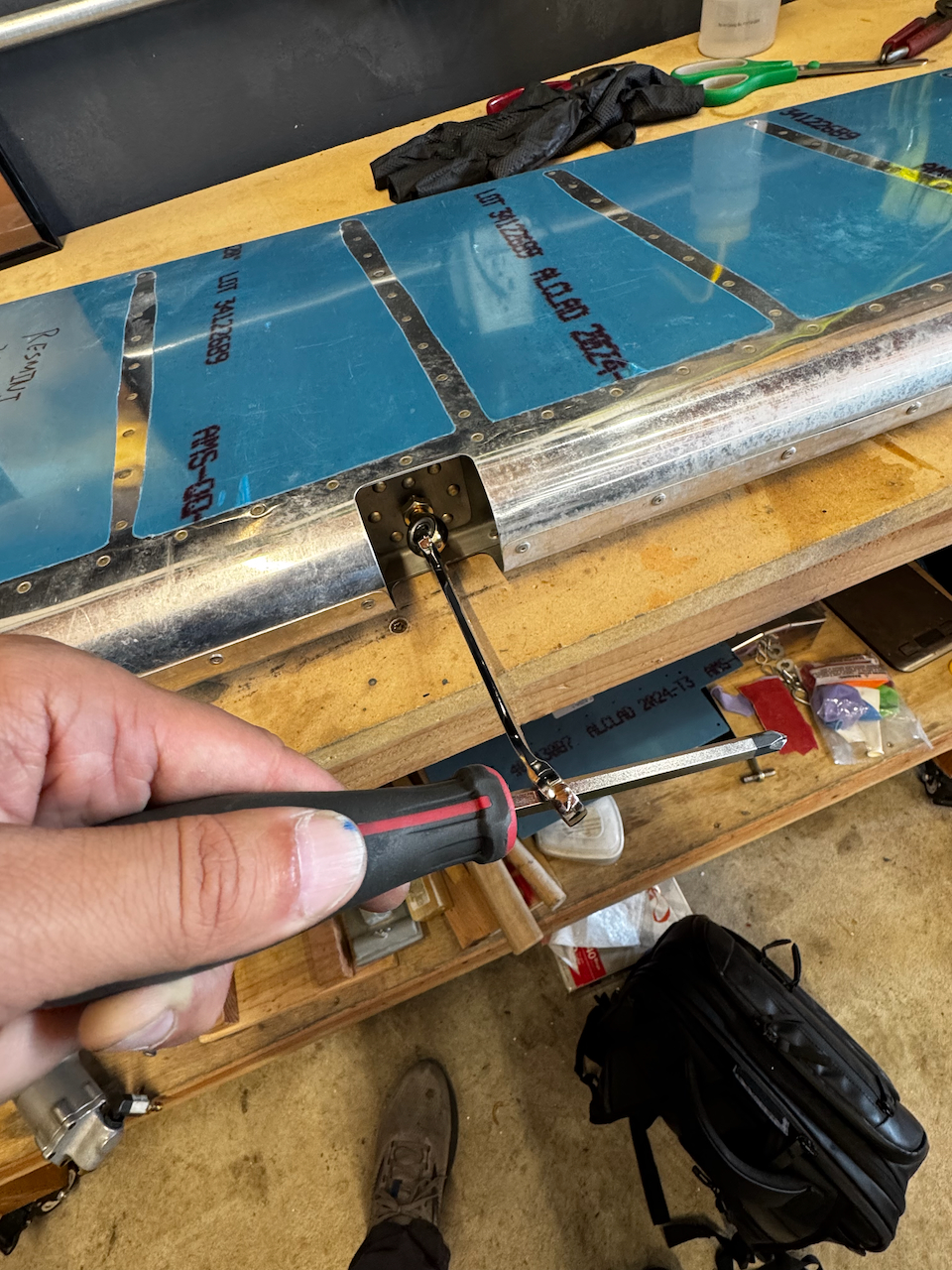
Using a rivet at the top I was able to secure measuring tape nicely
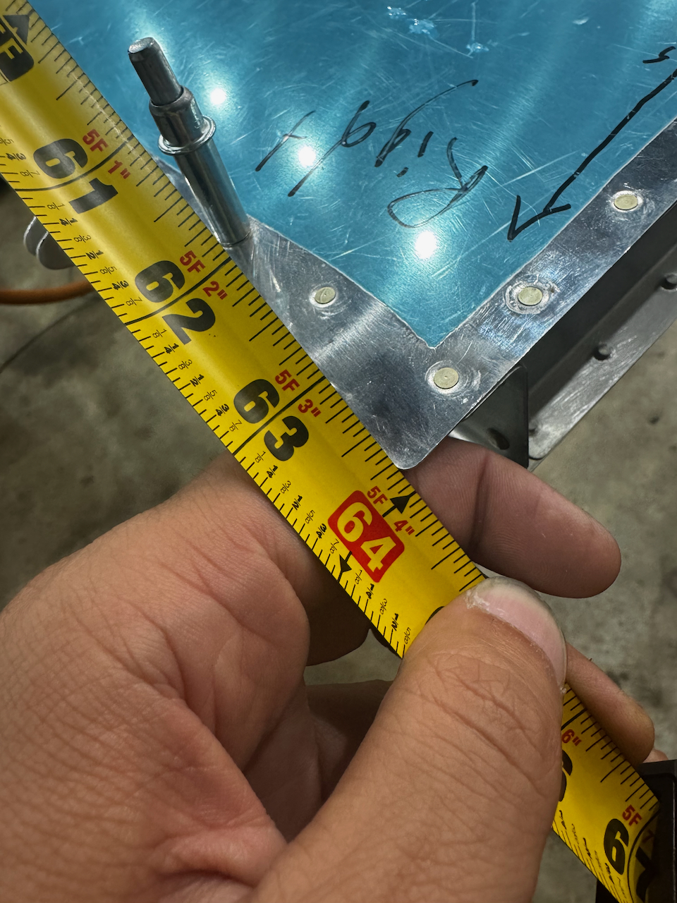
within 1/16 difference! Not bad.
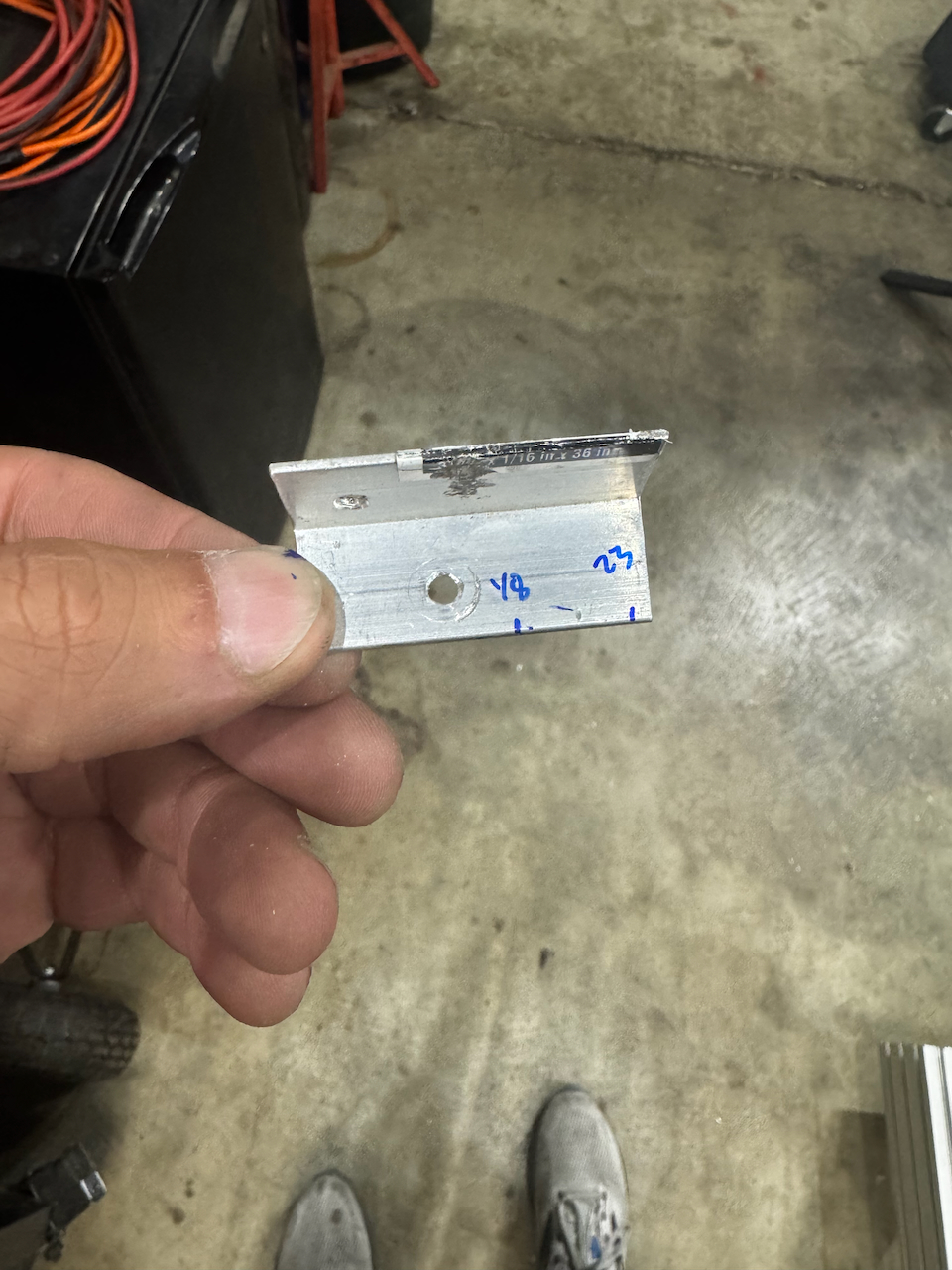
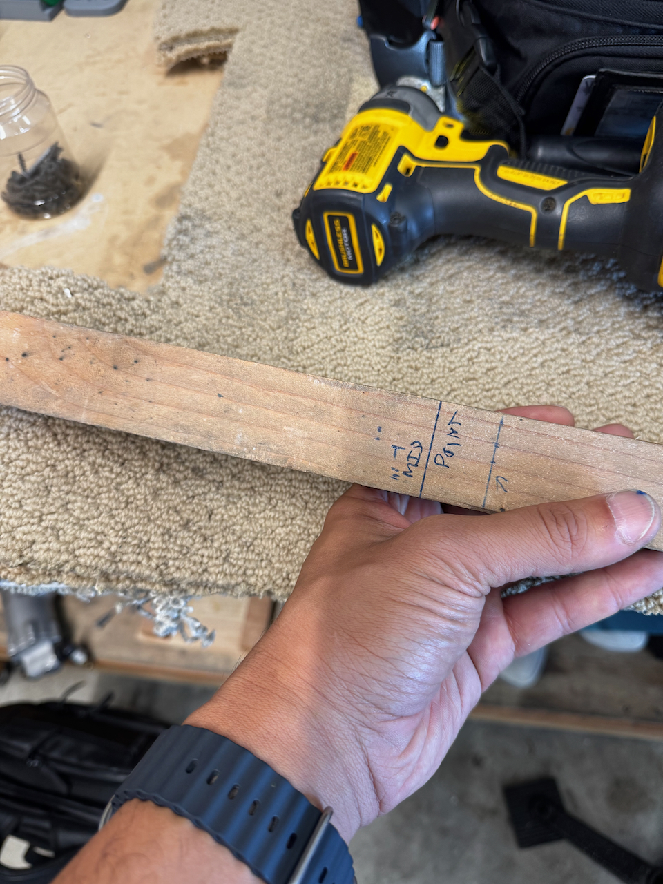
I had to make up a special measuring tool to get my drilling layout done.
it worked perfectly!
holes marked for drilling.
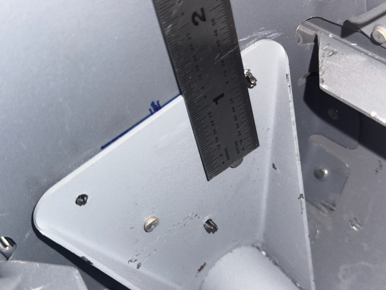
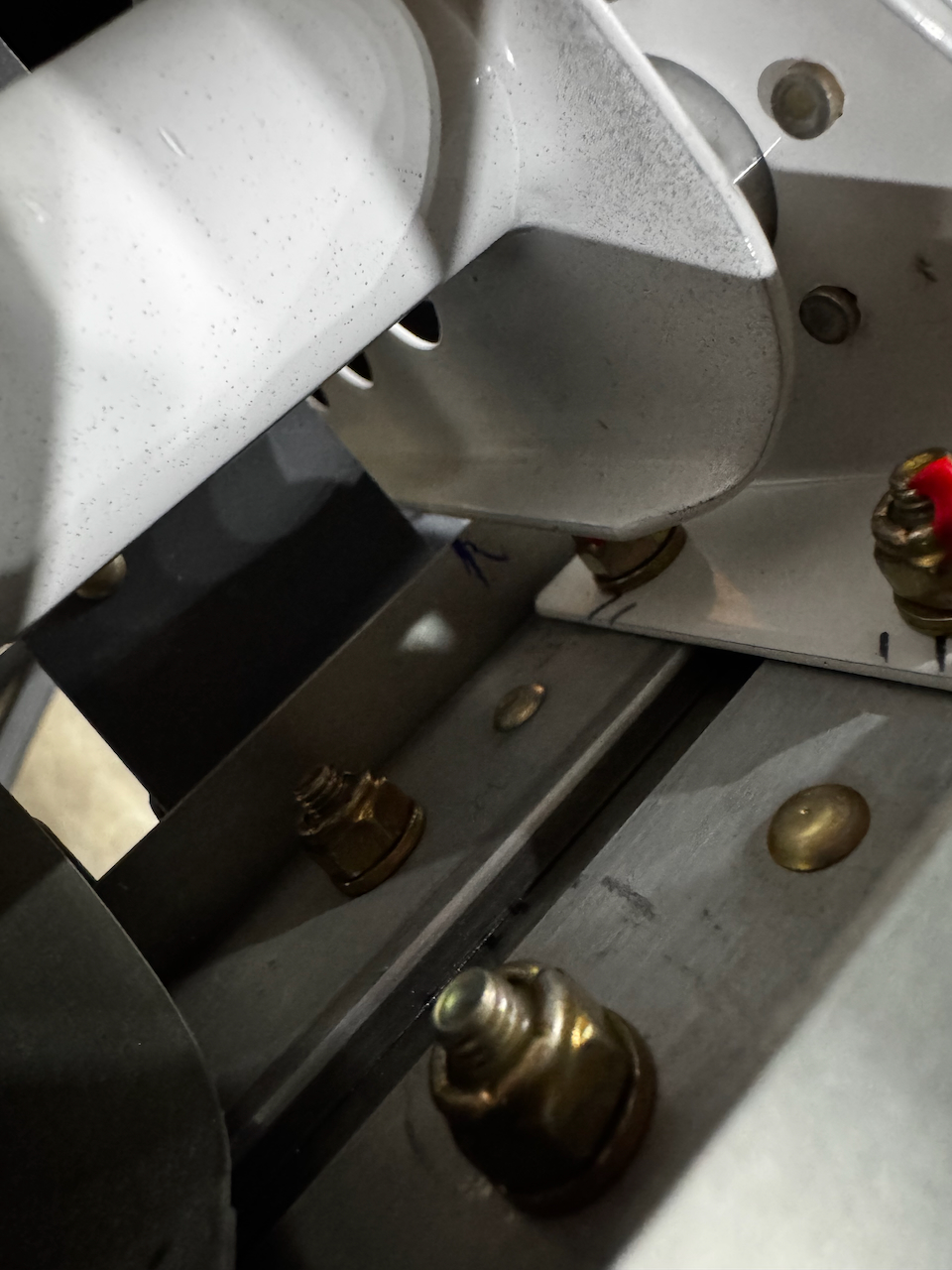
after drilling, edge distance verification. It’s close!
bolts are in!
wow… that looks cool.
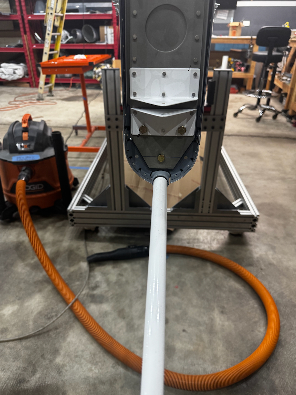
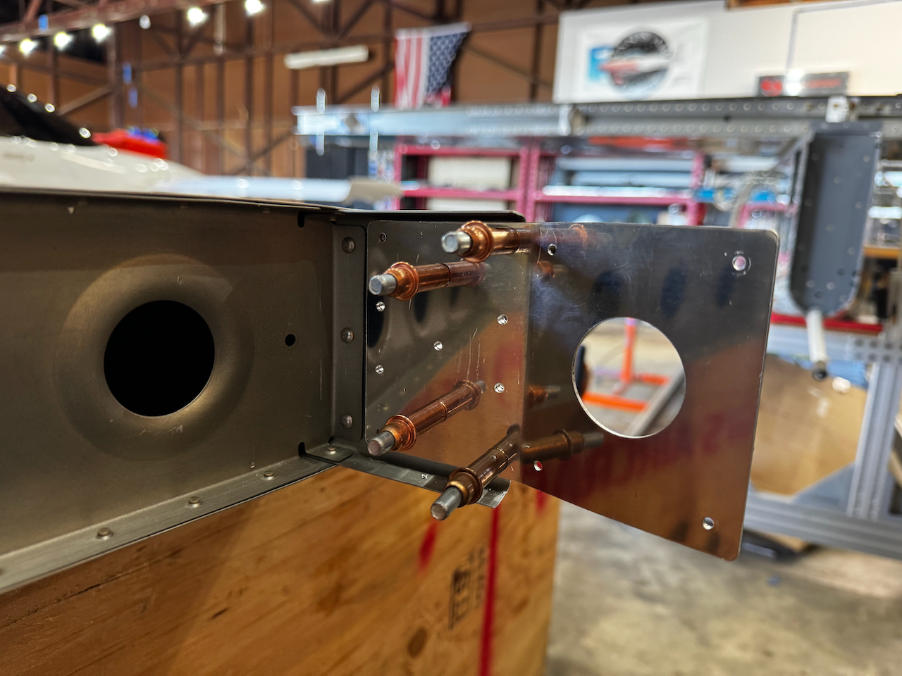
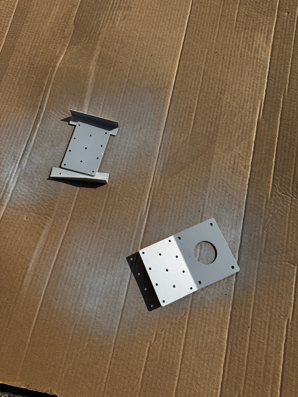
with the rudder square, I now had to center it along the fuselage centerline. It’s another interesting measurement exercise. The surprise here was how different the vertical spar alignment was laterally to get the centerline measurement to work. so much so that I quadruple checked the measurement. Trust the process right? After drilling the attachment plate (and spacer), I primed both and reassembled. I went with the spray can primer again. Outside of it being a different color, it’s a very convenient way to get through a few small pieces.
Centering instructions
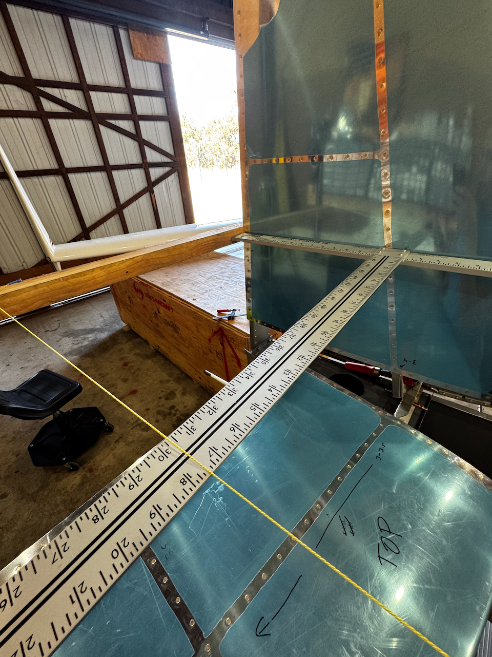
cross beam to measure centerline alignment
I used mason line as my reference line
conveniently. the line didn’t have any interference.
once again, measurements were within 1/32″ using the same rivet reference point.
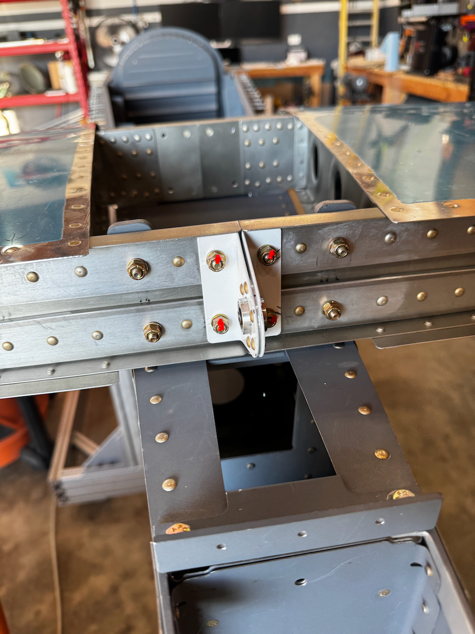
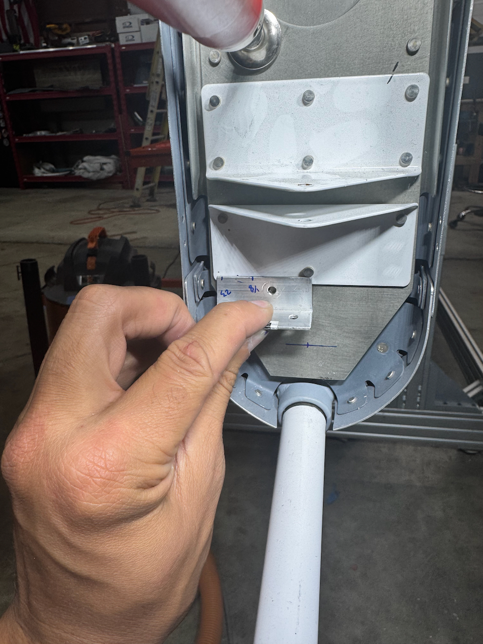
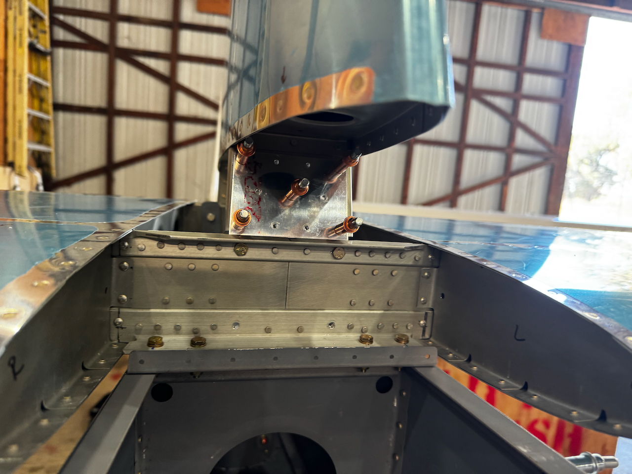
attachment plate used to match drill…
… some of the holes were not reachable without removing the stab and reversing the assembly to drill from the back side. Thanks for the idea Sam!
with front attachment drilled, I final size drilled #12 the aft holes and inserted bolts.
priming the easy way!
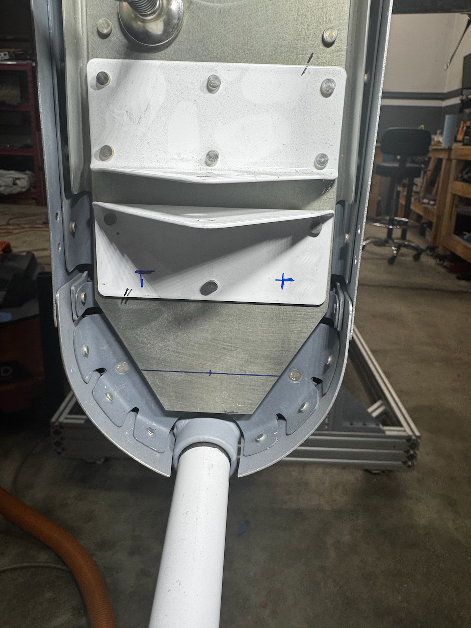
re-assembled and ready for riveting!!
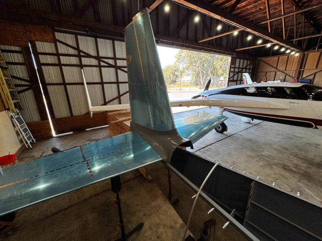
For giggles, I had to put on the empennage fairly and imagine what it might look like when ready to fly. Sheesh… it looks really cool.
I had a little time left, so started to play around with putting the elevators on. It turns out this is a TOTAL PAIN IN THE BUTT. Getting the Bolts to fit in properly was so frustrating I ended up going to the forums to get some tips. Turns out there are some cool specialized tools that make it a whole lot easier. Given that I’ll be taking on and off rudders, elevators, and ailerons quite a bit over the next year, I figured a few bucks (ok, maybe 50) would be worth the reduced frustration. They should be coming on Friday. Besides… who doesn’t need another super specialized tool only usable for one task??
elevator time!
Putting in the bearings
Once mounted I marked where I would need to trim to provide full motion….
… also on the outboard counterweight arms.
Although I forgot to take a picture of it… I swear I was able to get one of the elevators on the hard way. Next up will be continued work on the elevators… and some delicate drilling to mark the elevator swing locations. After that I get to build out the control system. Fun! Until then…. Happy Building!

2 comments
Hard Core
It looks like a plane! Congratulations on the progress. NICE job.