8-42: RV-8 Main Landing Gear and Tailwheel Installation
Build Crew:
Hours:
Sam
2.2
Giacomo
0.2
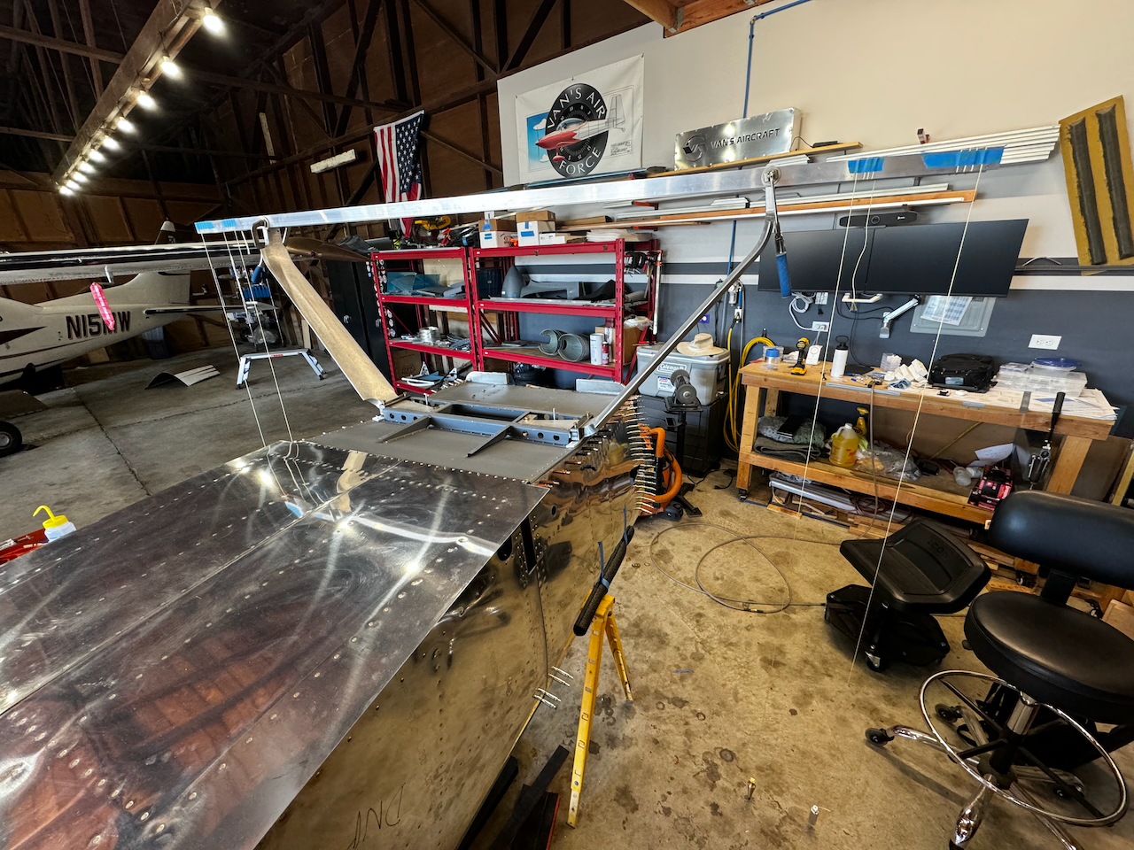
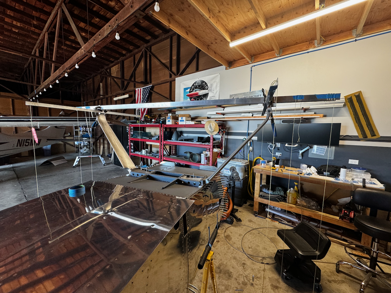
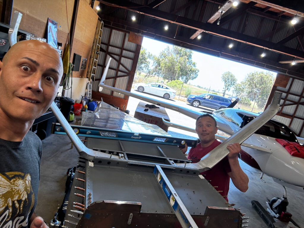
Landing Gear is another one of those milestone events. There’s something about putting legs onto your fuselage that makes it feel more like a plane. Yes, this time around will only be temporary as there is much work to be done before they are permanently installed, but the plans call for fitment to occur now. I opted for the Sky Design Aluminum airfoil landing gear. These are one piece landing gear that avoids having to deal with the fairing, have the brake line gun-drilled right into the gear, AND save you 15 lbs… not bad. Did I mention they are absolutely beautiful? I had previously inventoried them, so now it’s time to get them on to this plane!
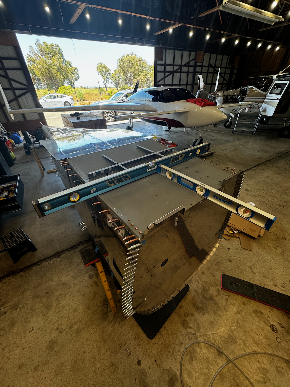
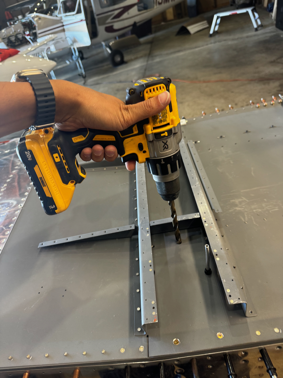
First things first, I needed to level the fuselage laterally and longitudinally, then final drill the main bolt hole for the inboard bracket. This will be the anchor as all the other alignment is done.
Plans call for a level fuselage laterally and longitudinally
FIrst of many drillings!
Match drilling the inboard wear plate
Looks ready to install!
Landing gear are on!
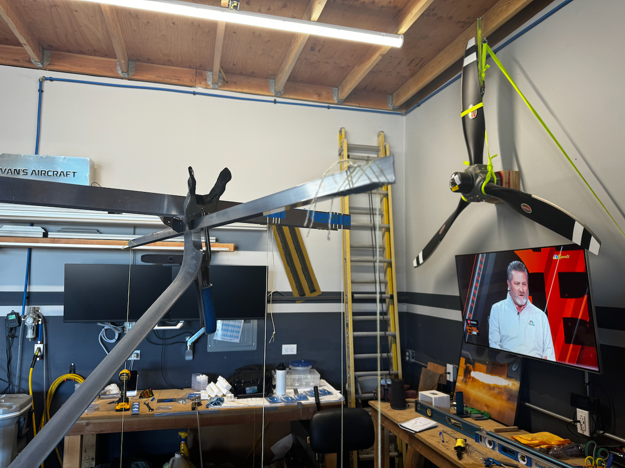
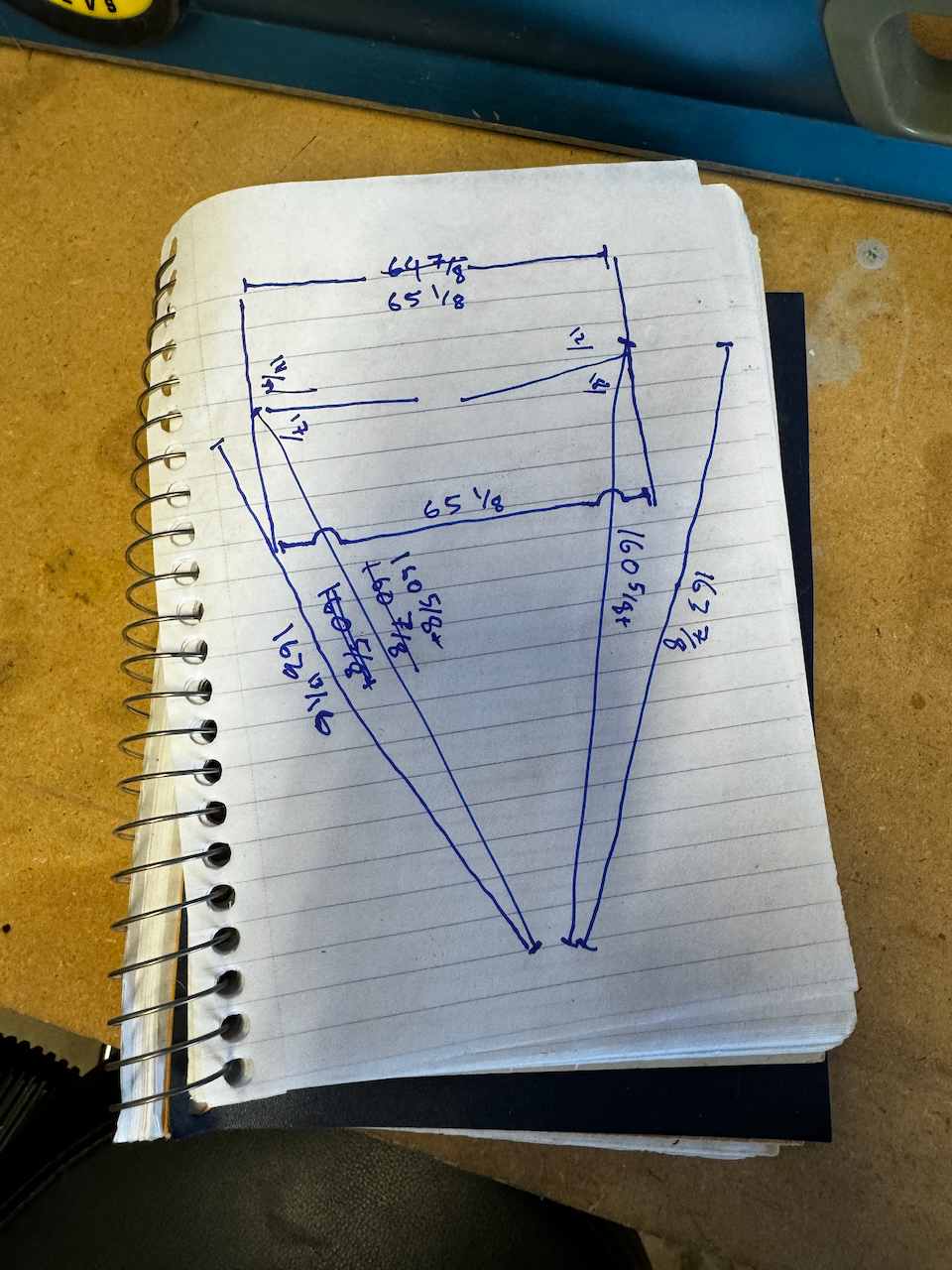
With the landing gear on with the one main bolt, the hard work starts. The main task of landing gear fit and alignment is ensuring that the gear legs are perpendicular to the fuselage, with no toe-in or toe-out. This can be done with a little geometry, using the theory of the isosceles triangle. If we can ensure that points on the landing gear are equidistant to a common point at the tail (the “reference point), and if those gear are aligned in a straight line, that guarantees they are perpendicular. Since I was using the Sky Design after market gear, the method for achieving this is slightly different from the plans. By using some aluminum angles and clamps to align the legs, you can project their location using plumb bobs, and measure over the ground.
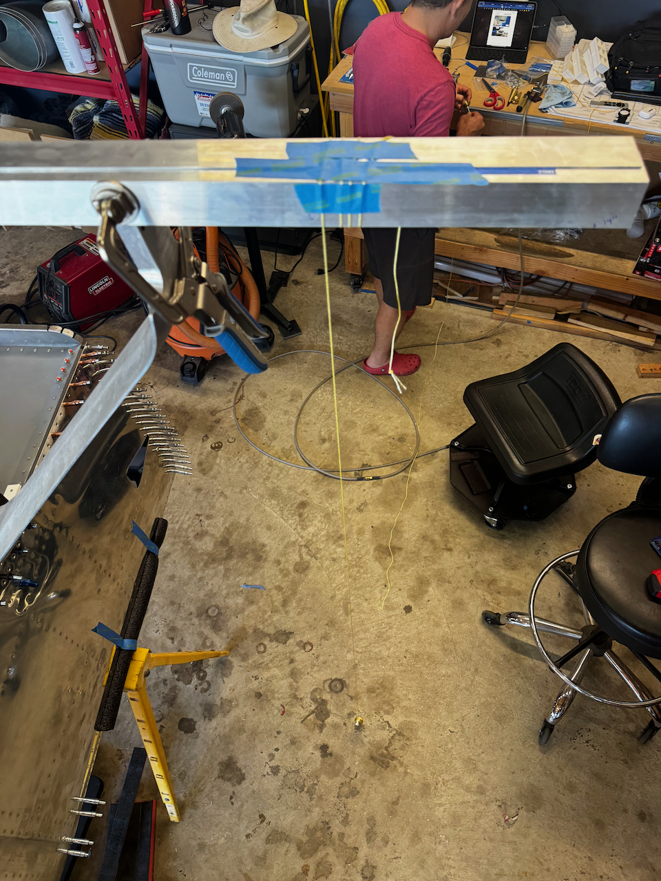
Aluminum Angles clamped on to align gear.
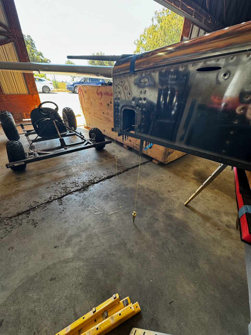
Plumb bobs for measurements
and rear reference point
all measurements are taken from the plumb bobs to the same reference point at the tail.
Even though I used the aluminum angles, and even if measurements are equidistant to the reference point, there is a slight chance that the gear are not aligned perfectly resulting in both gear sweeping forward or aft. This can be detected my measuring the toe-in or toe-out of the face where the axles are mounted. By attaching additional angles, we can measure this toe-in.
Angle mounted to the axel mount face allows measurement of toe-in/out
both sides mounted with plumb bobs dropped.
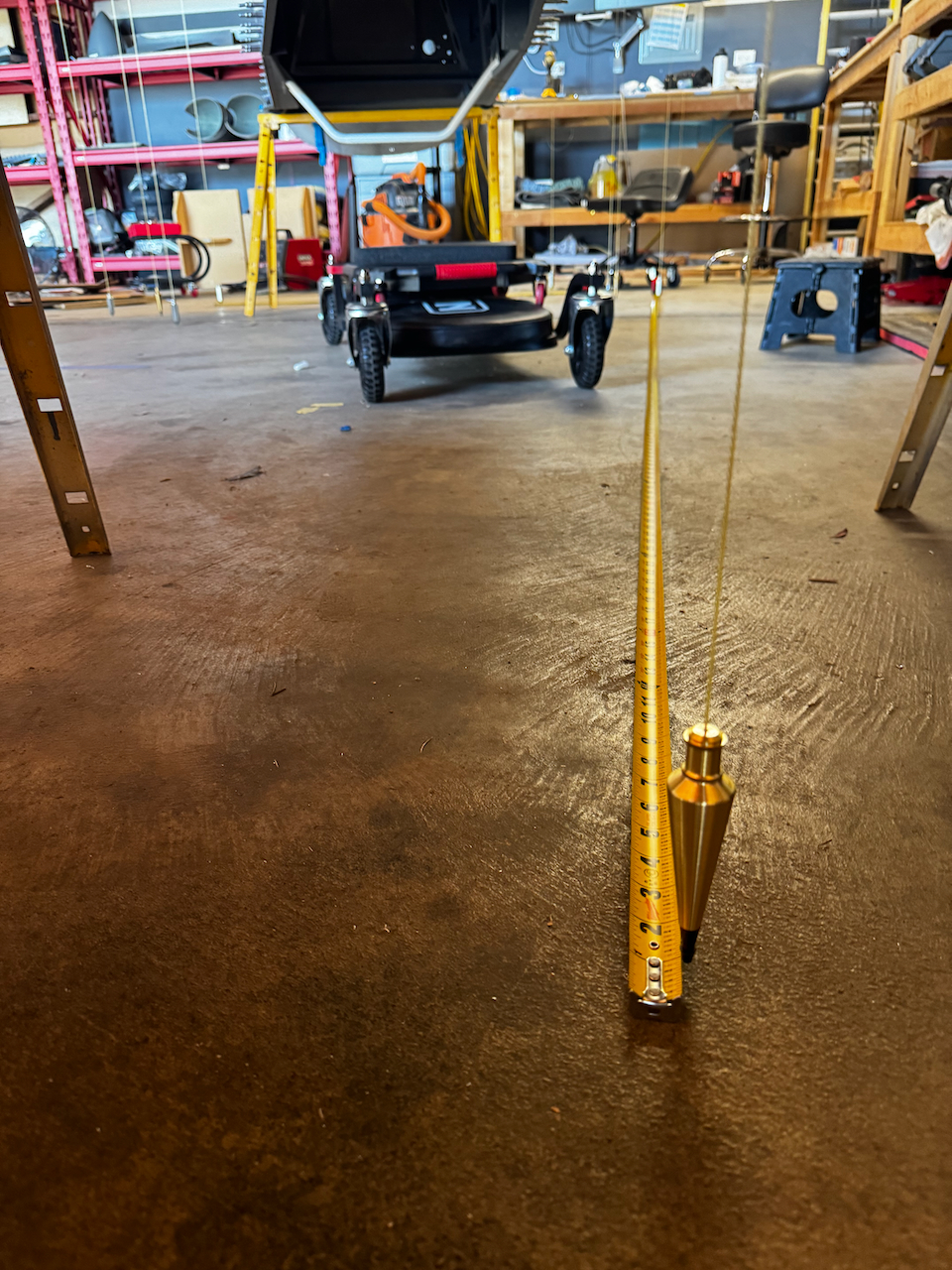
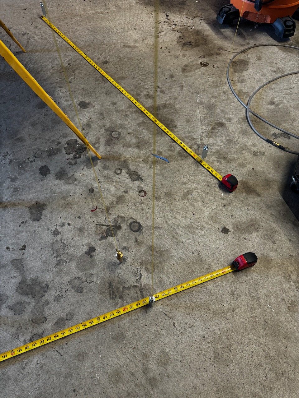
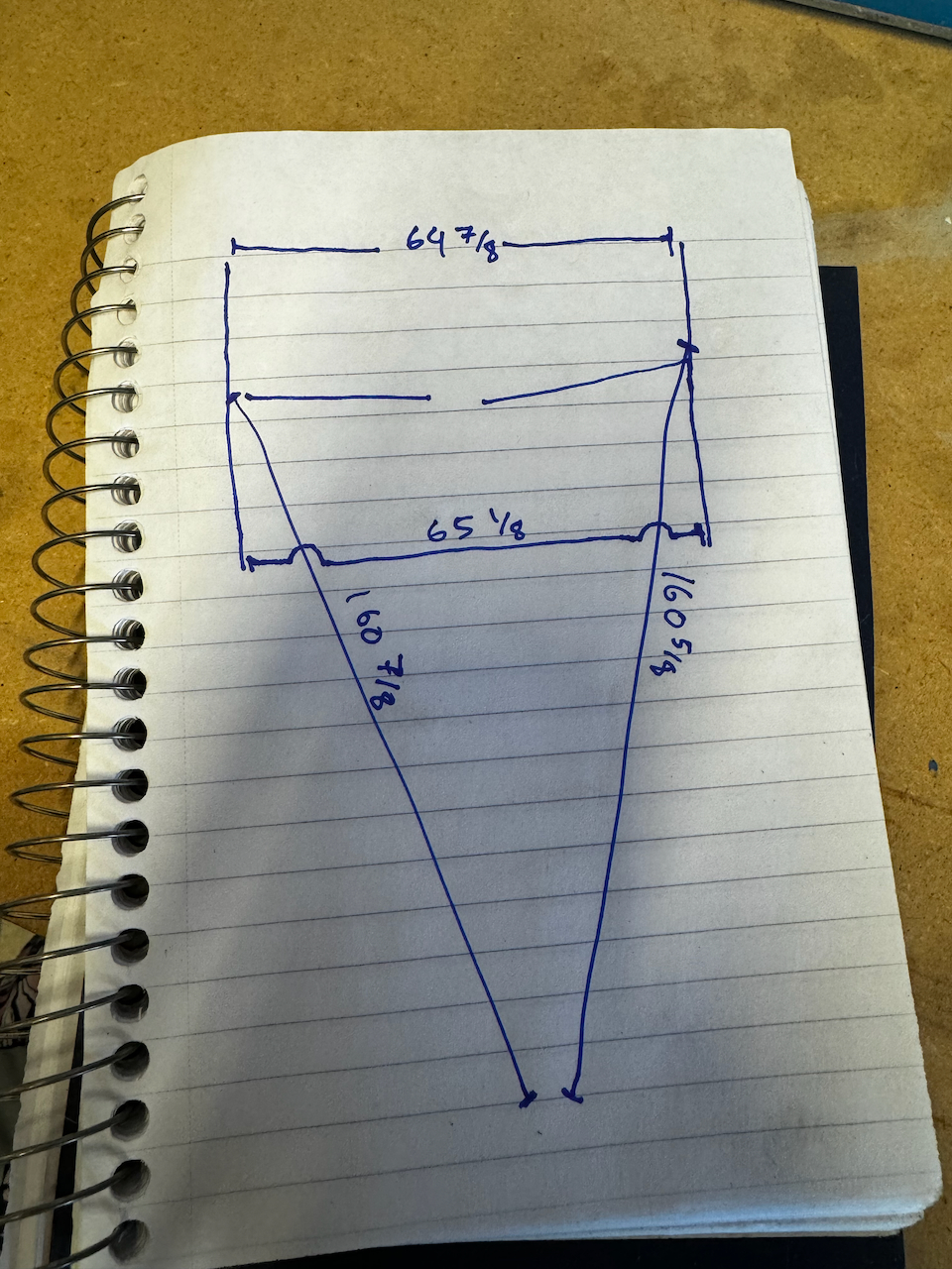
Then, we can measure toe in/out and distance from reference point at the same time.
Toe discrepancy and distance to reference point have a bit of an interplay (changing one dimension affects the others), so I measured all distances before making any changes. Then I was able to make a few strategic adjustments to get everything within 1/16″ of ideal. This is probably as good as it gets with the margin of error that comes with plumb bobs and my bad eye sight. As you can see, after a couple tries, my measurements ended up quite satisfactory.
Initial measurements… within 1/4″.
After some tweaks, worst deviation was 1/16″. I think I can live with that!
With everything aligned, Jack and I tightened down the main bolt to hold everything in place. That being said, I don’t want to wait too long to do the drilling lest something gets out of whack. I plan on getting to that this week with a little help from Sam and Nico. Until then…. Happy Building!

2 comments
Finally a good use for geometry 😂. Nice progress
what would you do with if it was out more?