Lots in this post. I’ve been knocking down a ton of fun projects getting the various systems hooked up in the fuselage. Elevator, Elevator Control System, and Rudder install were all part of the docket. Various photo and commentary sections follow. Enjoy!
Elevator Horn Repair and Install Completion
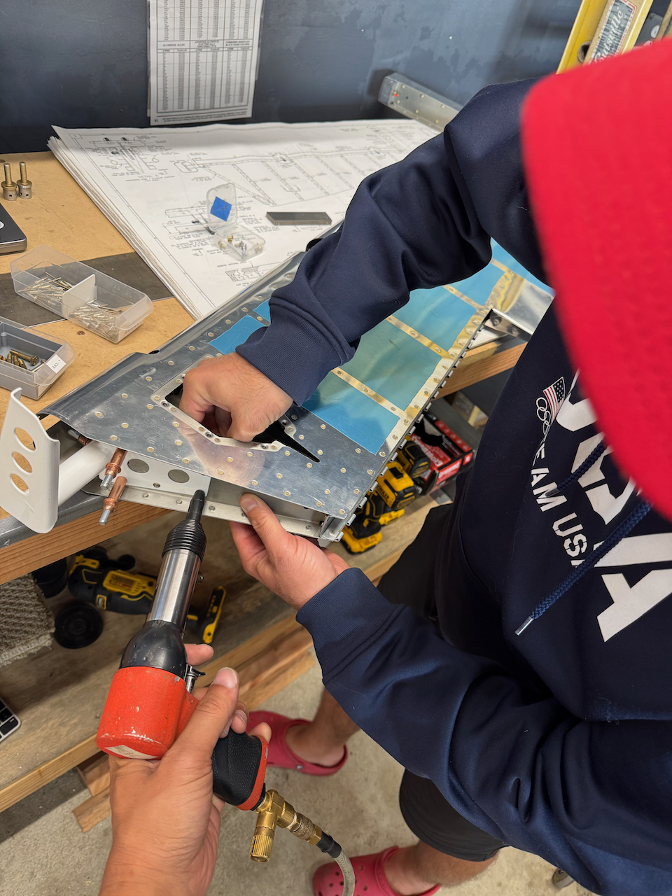
A couple weeks ago I posted about my blunder with the left elevator horn. Because I didn’t measure the distances for the rod end bearings, the elevator ended up being to close to the horizontal stabilizer causing my hole location on the horn to be incorrect. Thankfully, It was an easy replacement and after getting the part I got back to work replacing, and then redrilling the horn. This time with the correct measurements! Sam helped with the bucking as there were slightly awkward access options.
The drilling went smooth this time and I definitely triple checked my confidence that I would be able to get a nut on the end of the bolt before I drilled the hole.
New Elevator cleco’d on
Sam helping buck
Elevator re-installed!
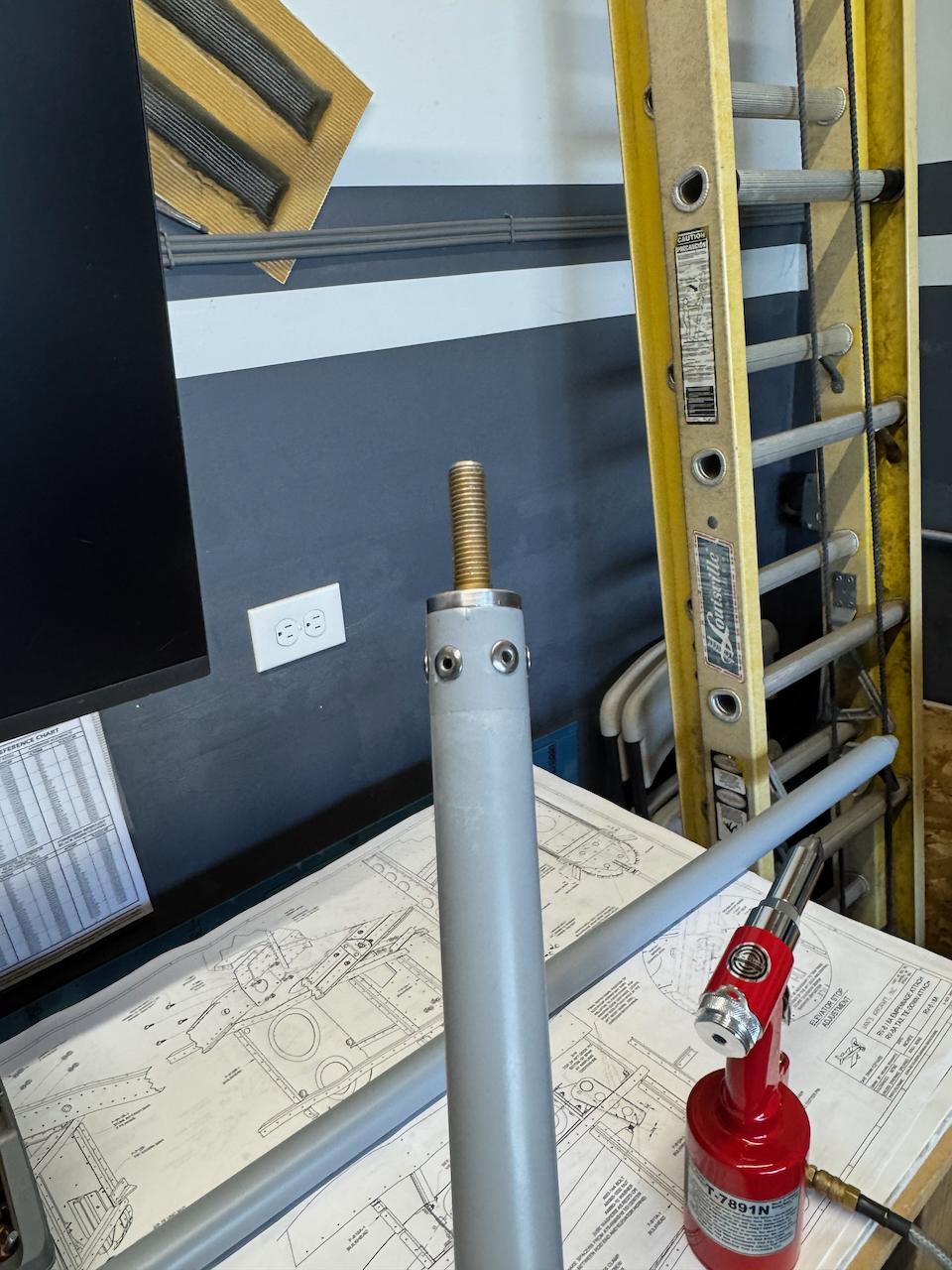
Mounting elevator for horn drilling…again.
WIth proper distance on the rod end bearings, hole location looks correct.
using the drill bushing for marking hole location
time to drill!
Looks good!!
finalized spacers for elevator center hinge
Elevators installed!
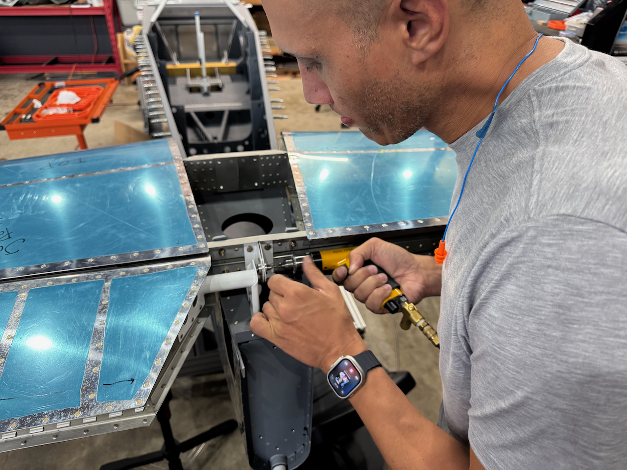
Elevator Control System Connection
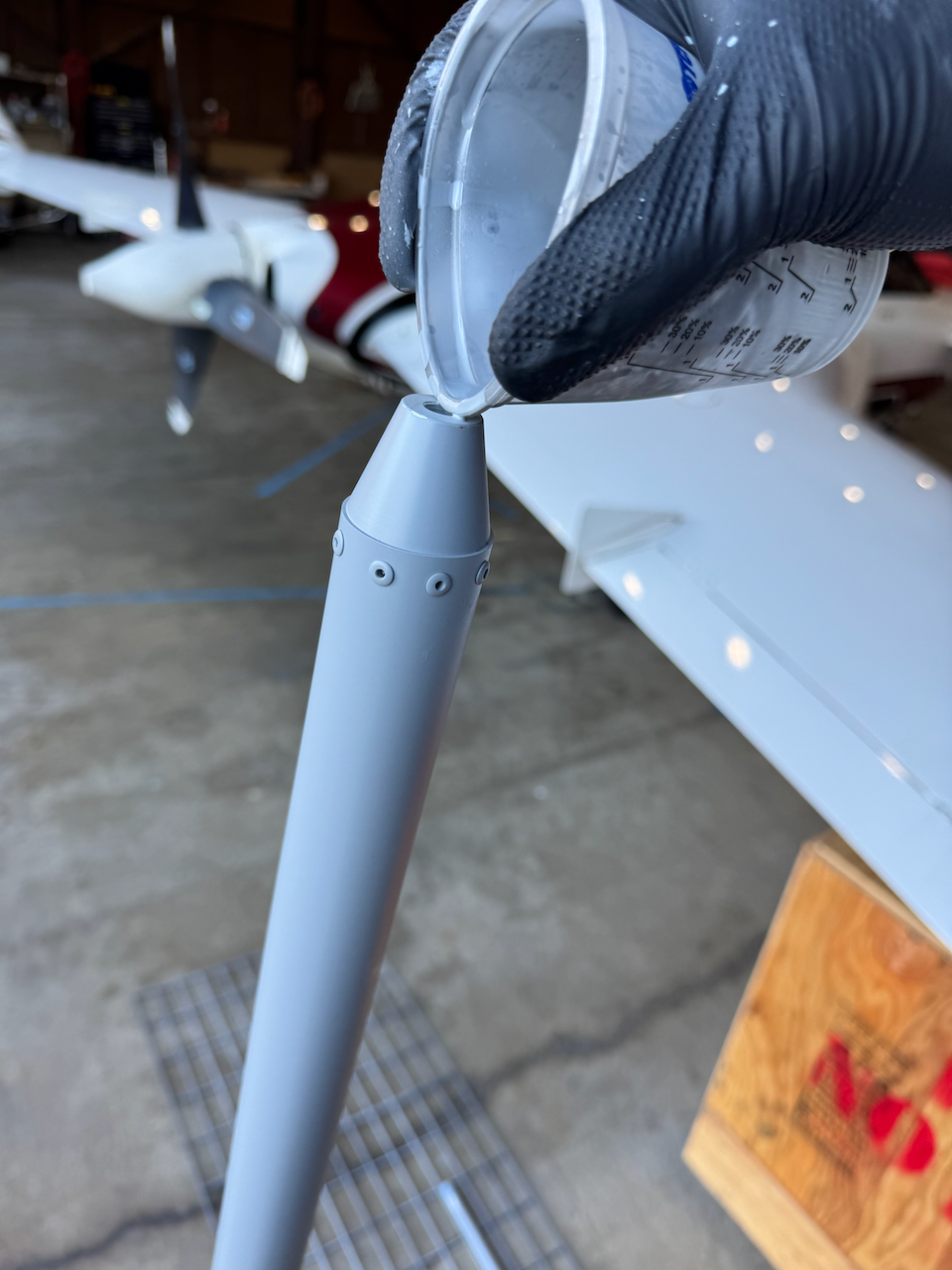
With the elevator now cleanly installed, It was time to install the control system. Basically, the series of push/pull rods that take the control inputs from the stick and translate that to elevator movement. I needed to prime the push rods and had to prime the interior of the rods. I did my best pouring the primer into the rod, sealing the ends and then swishing the primer back and forth. It was a fairly messy process as I wasn’t able to fully seal the ends so primer got all over the place.
Priming control rods and bellcranks
messy work priming inside of rods
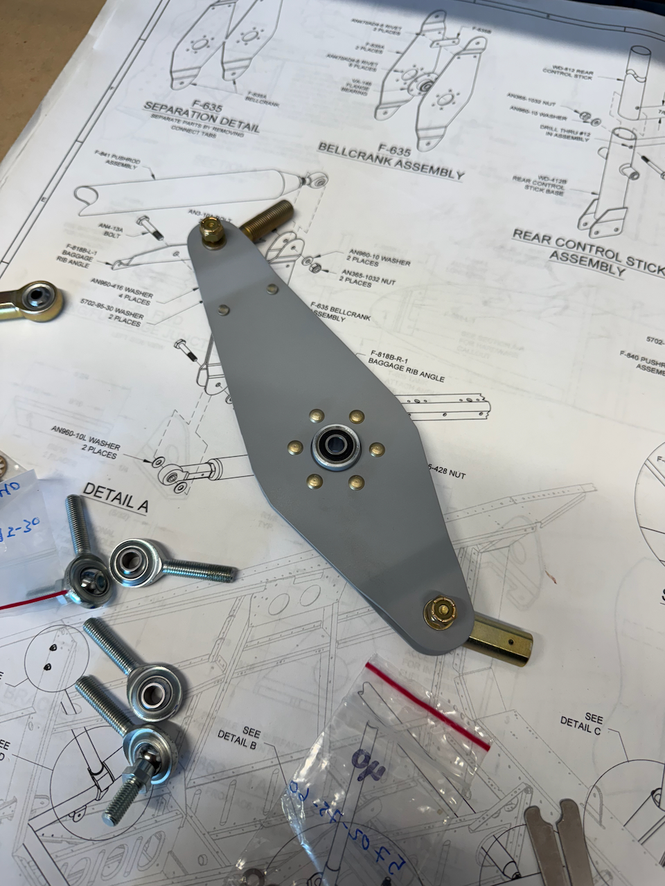
assembly of push rod after prime dried
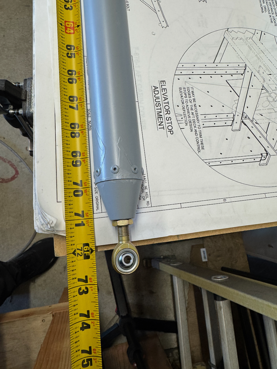
careful measurement of expected lengths
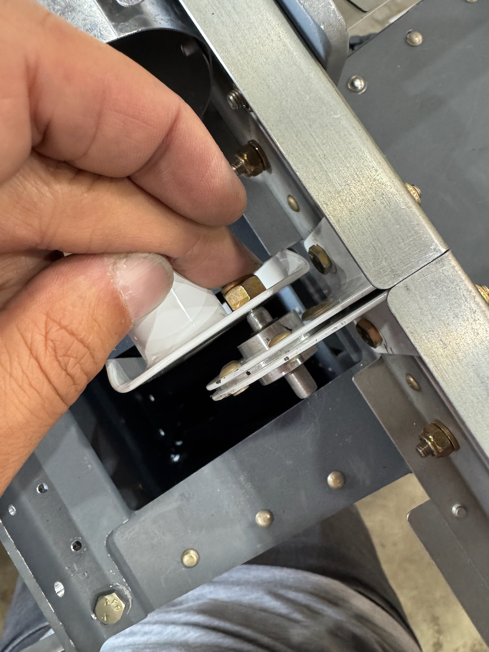
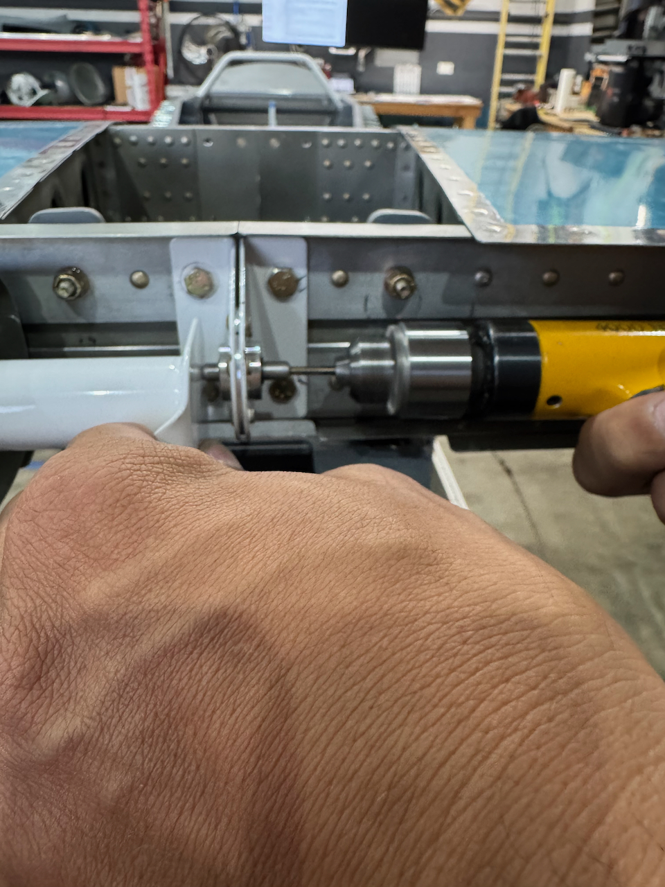
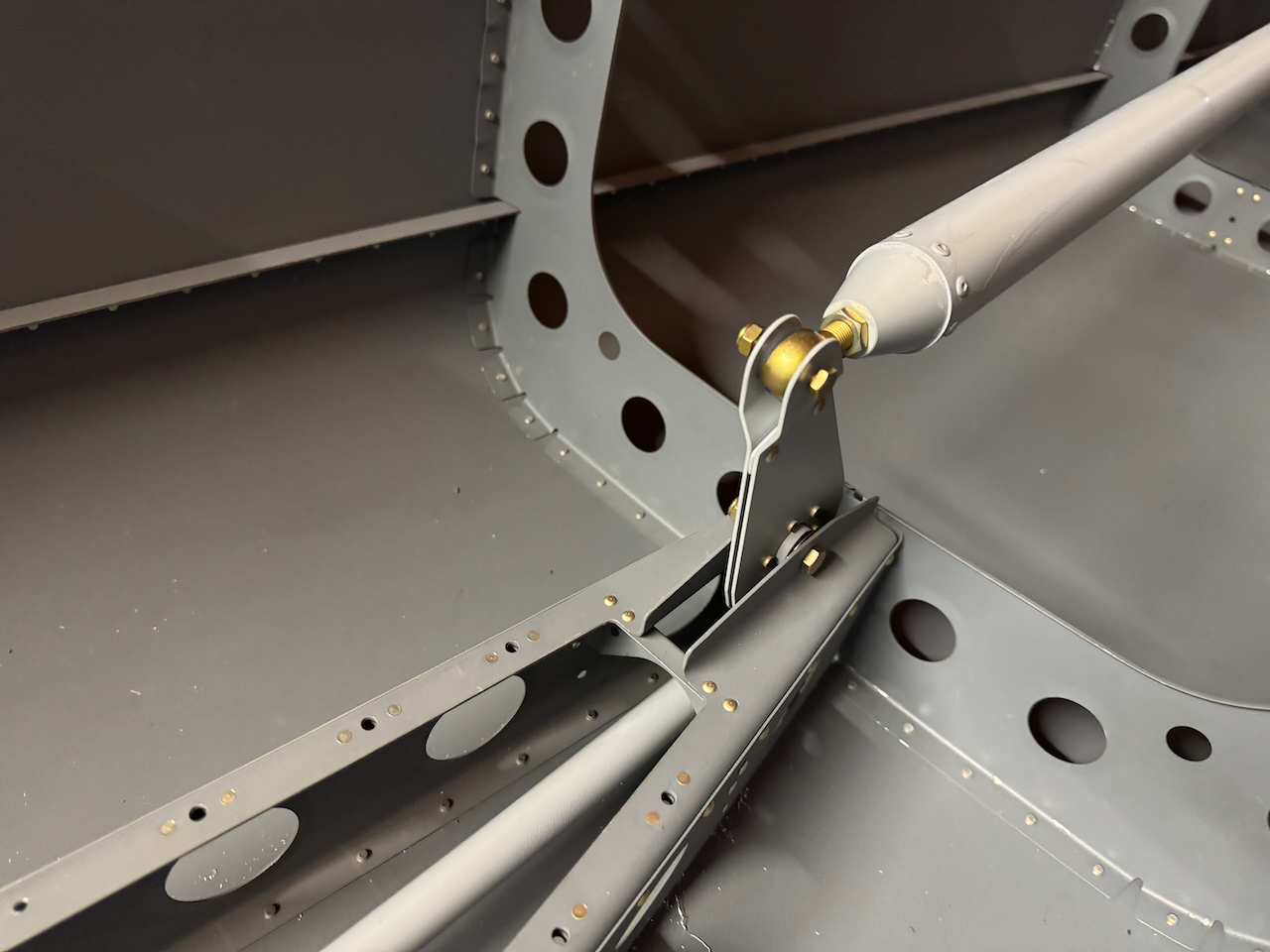
Once primed, I installed the control rods and made the holes in the elevator horn to complete the connections. Nothing big to report here except to take your time and follow the instructions. There are series of straight forward steps to get the horn holes to line up. After everything is connected you have to verify that the control sticks are vertical when the elevator is in the neutral position. And of course… you’ve got to play with the elevators!!
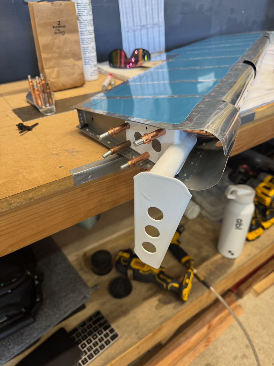
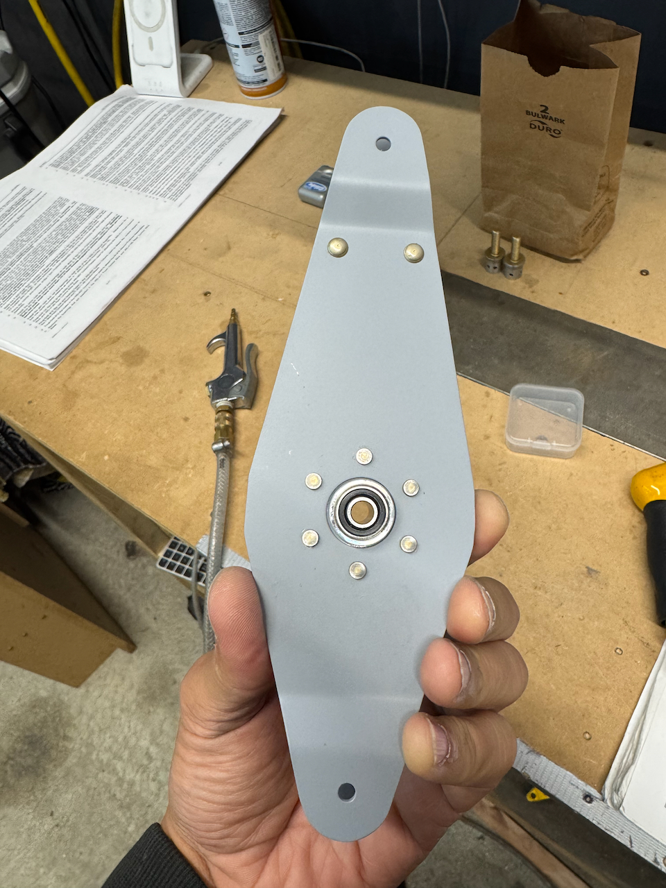
elevator bellcrank assembly
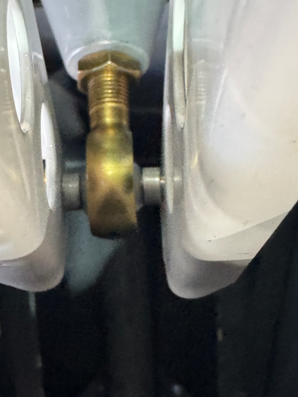
rod end bearing test fit
marking per plans initial hole.
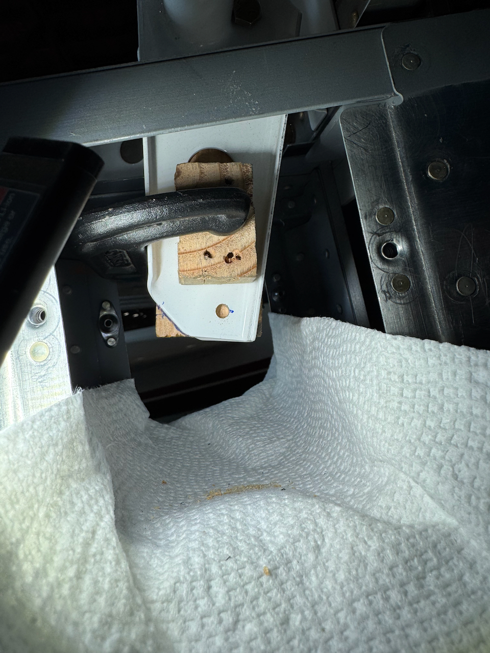
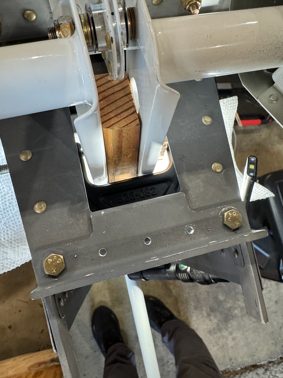
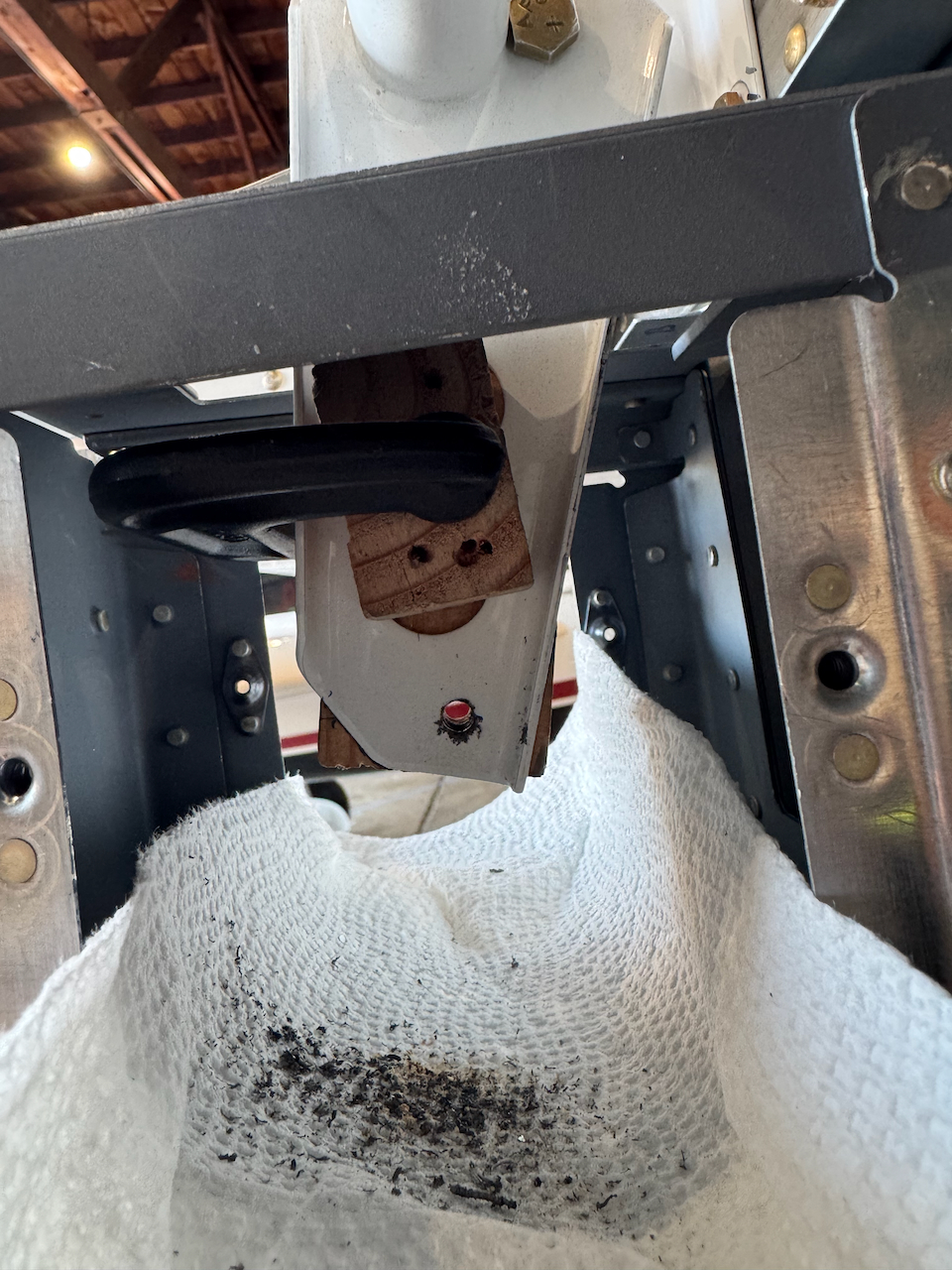
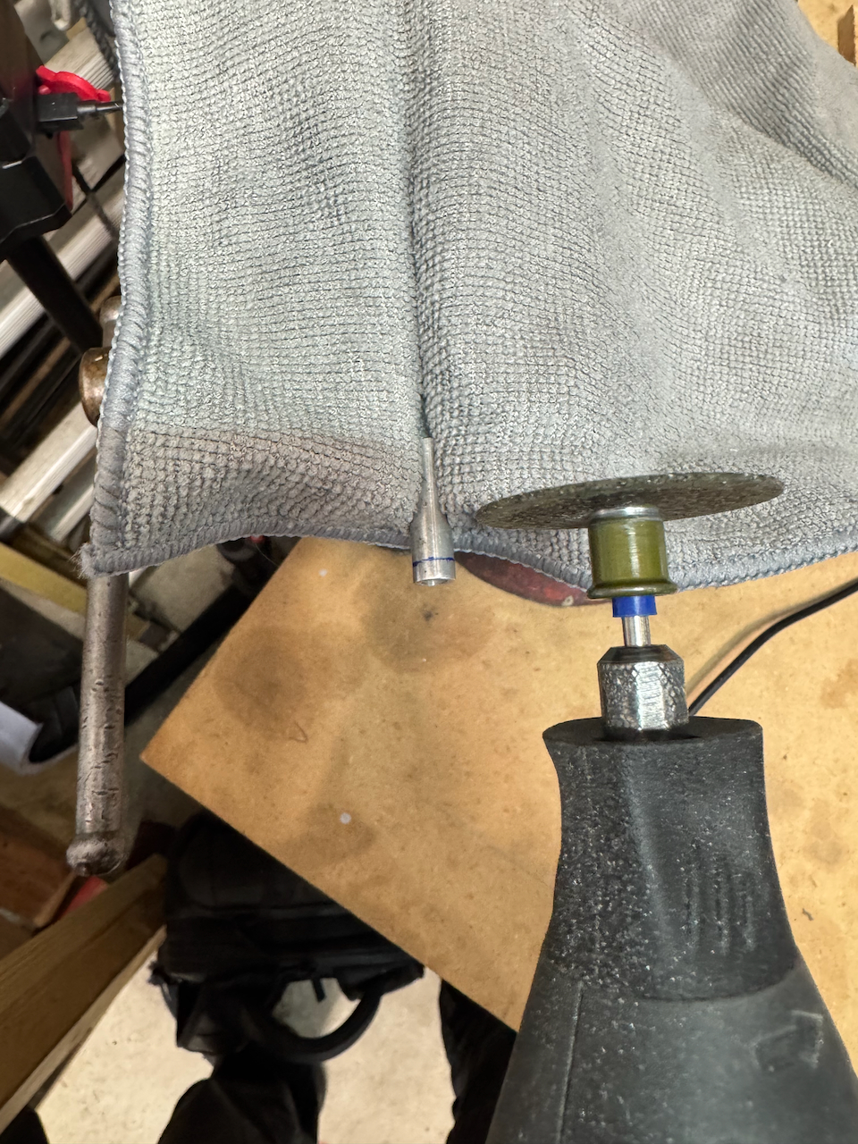
creating a block for drilling through to other side
nice tight fit for accurate location
holes drilled! note towel to catch shavings.
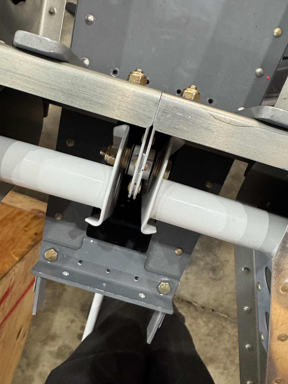
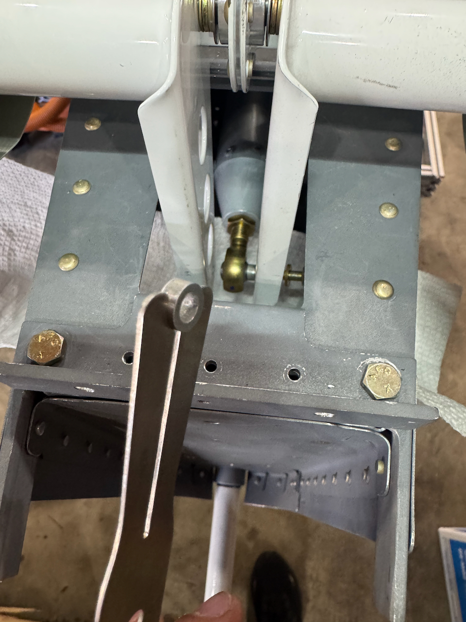
bellcrank attached at both ends
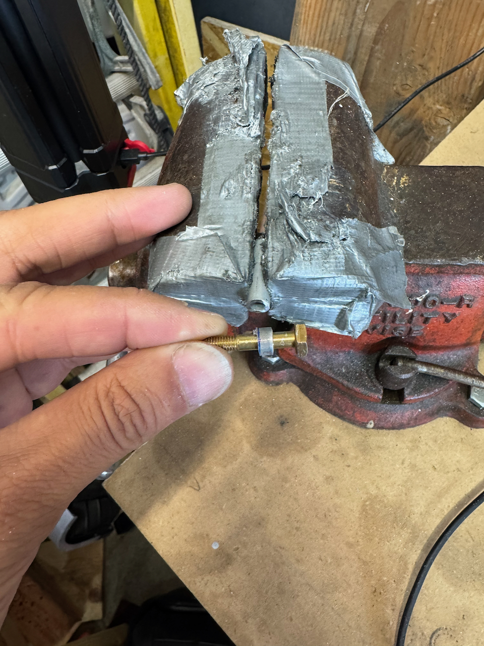
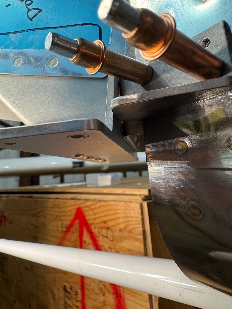
creating spacers for the elevator horns
nice!
fit looks good!
nice and tight… time to test!
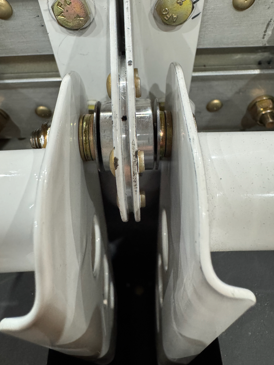
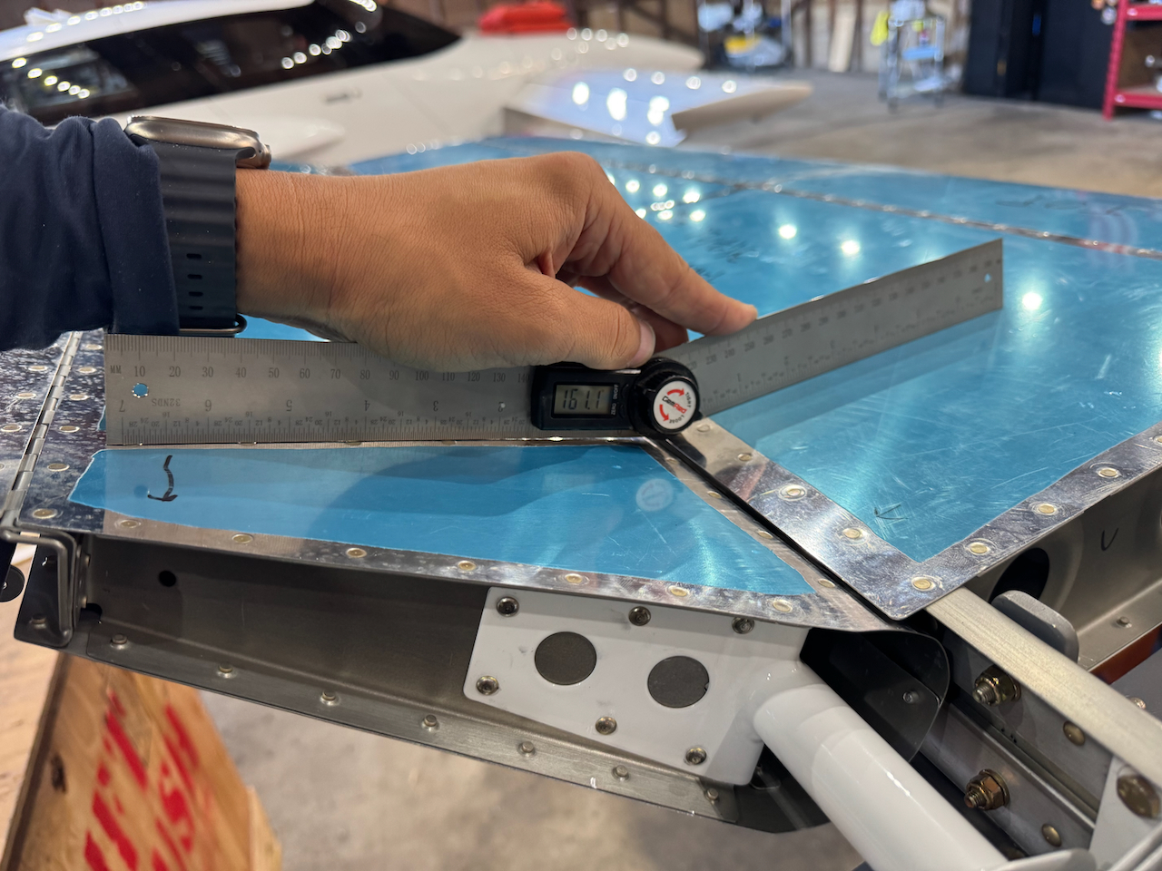
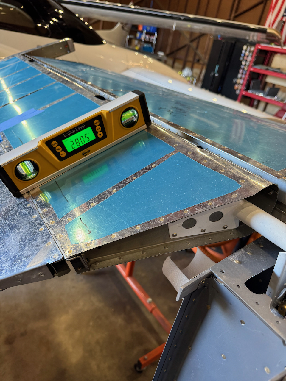
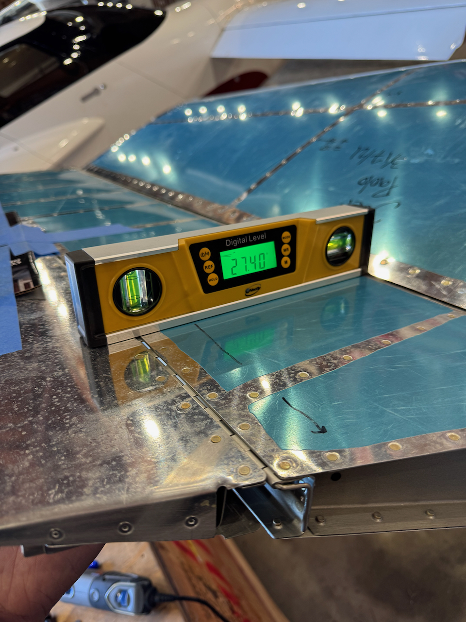
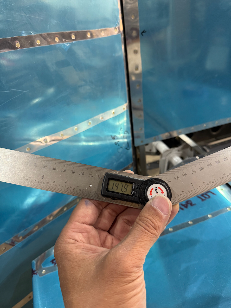
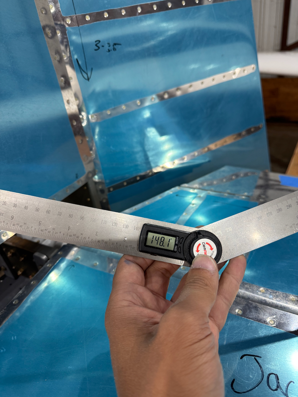
Next up is ensuring the deflection of the elevators are within the envelope defined in Section 15. For Up, this is defined as 25-30 degrees. For down, this is 20-25. There are two elevator stops fore and aft that you essentially trim until the deflections are satisfactory. For up deflection this was pretty easy but I was surprised how much material I ended up taking off. Down was a different story. The deflection I measured before removing any material was over 27 degrees. This basically meant I wasn’t going to be able to remove any material, and worse, I would have to add material to get within tolerances. This felt weird to me. I checked on the forums and it turns out it is not uncommon. There were all sorts of suggestions from “it’s not a big deal.. just leave it”, to adding material via complex riveting. I talked with Van’s directly and in the end decided to order some equivalent metal stock that I could fabricate into the appropriately sized elevator stop. This will give me the available material to get the deflection where I want it. Ideally right in the middle of the envelope. So for now, up elevator stop is set, and down is pending the new material arriving.
verifying elevator deflection
digital level was way easier. Note down deflection is too much
lots of trimming aft elevator stop to get to good Up deflection
Up deflection satisfactory!
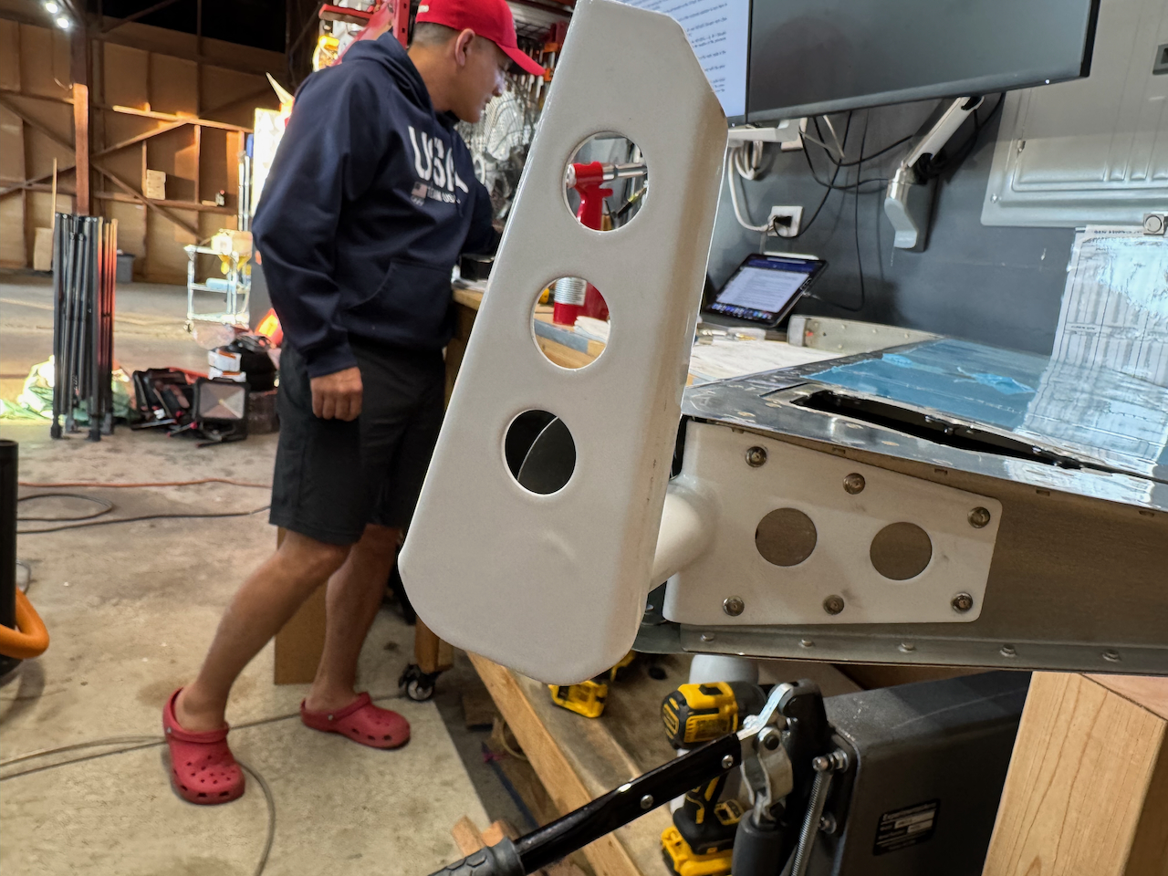
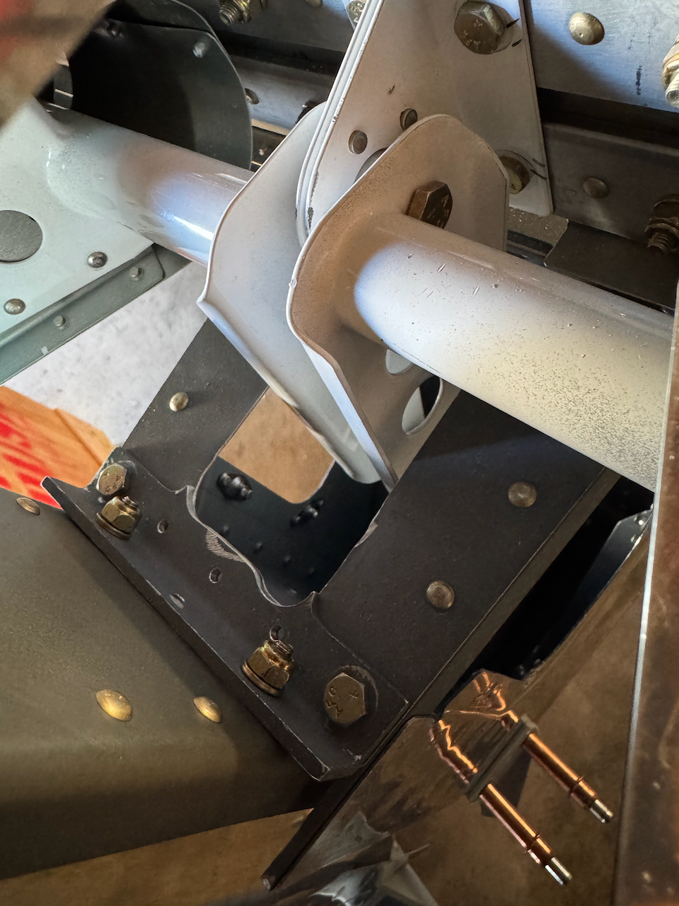
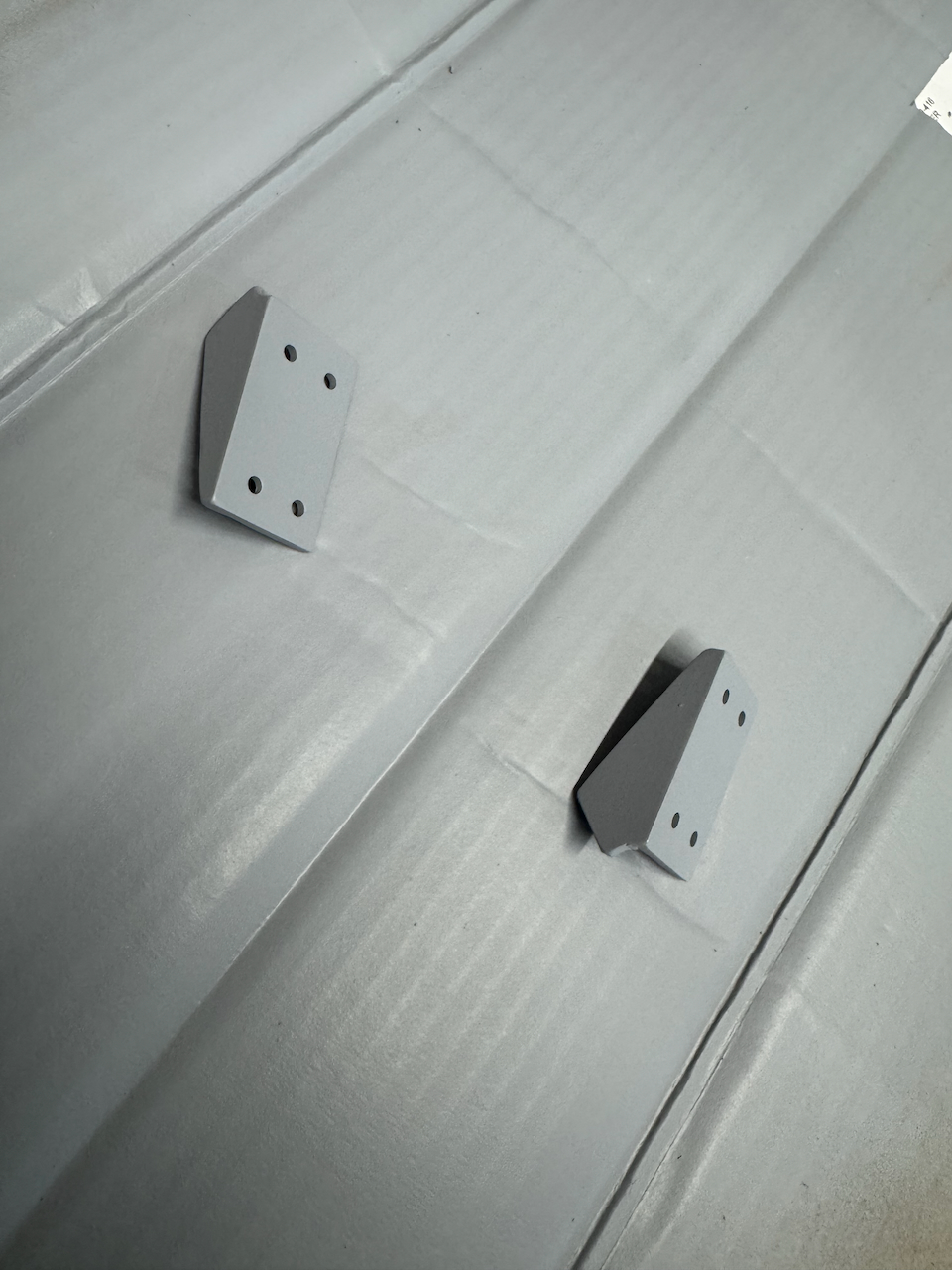
Rudder Stops
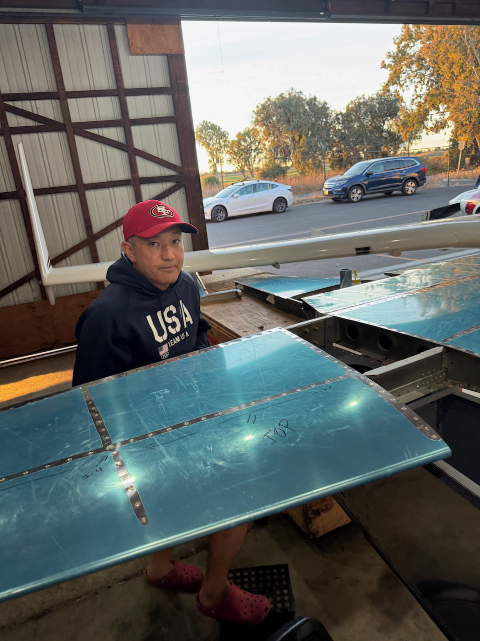
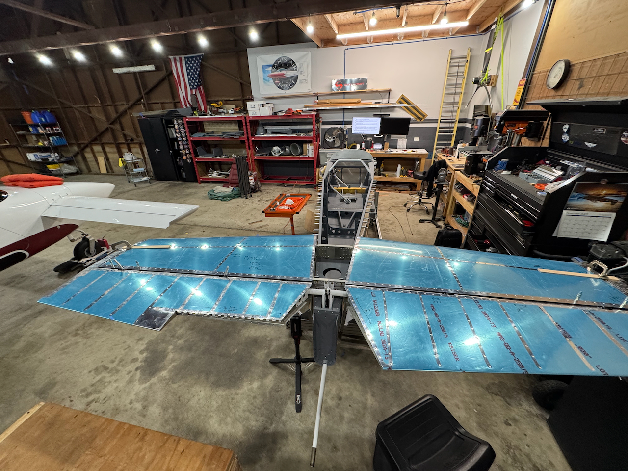
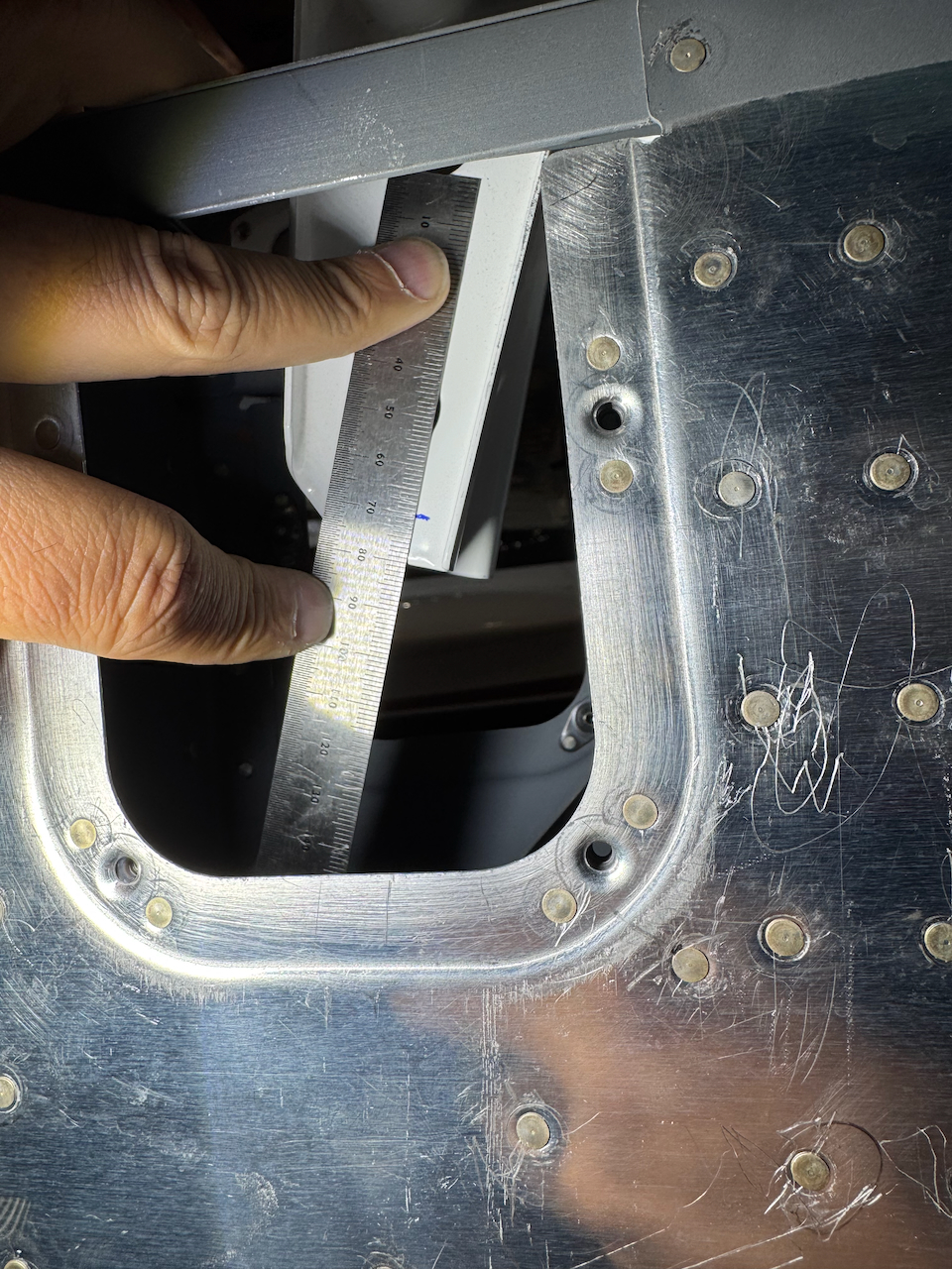
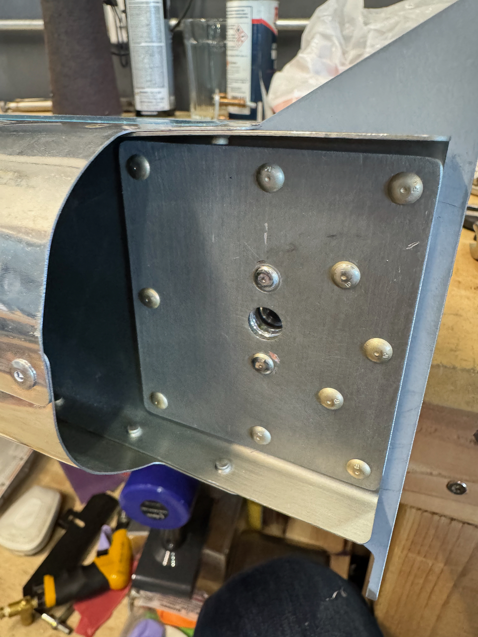
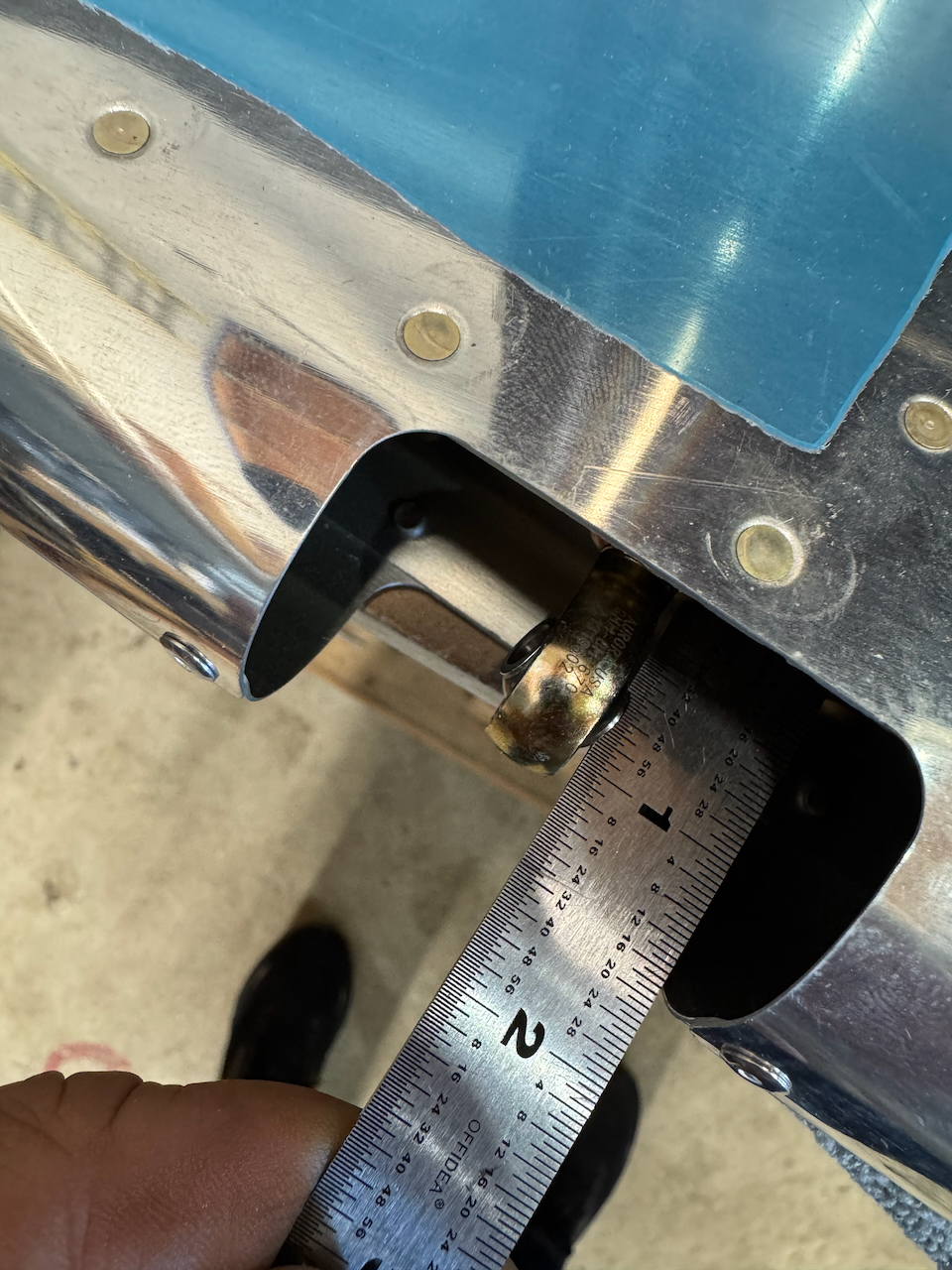
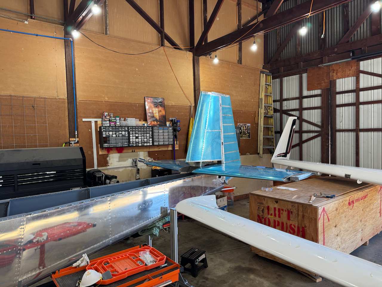
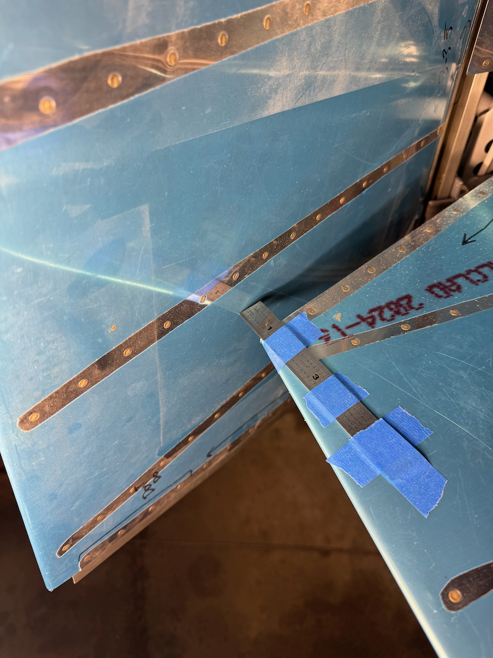
Since I was blocked on continued elevator work I decided to move on the rudder. It was the first time the rudder was going to be put on so I was excited to see what that looked like. Spoiler alert… IT WAS AWESOME. Seeing the full Empennage build up was exciting, and really started to give me the impression I might actually have myself an airplane some day. After getting the rod end bearings adjusted as per plans, and tweaking them slightly to align with the hinges it was time to trim down the rudder stops. (I did run into one issue in the rod end bearings. The lowest one was not aligning to the nutplate, so I removed and reinstalled the nutplate with better alignment) The theory is the same as the elevator… you have a defined deflection envelope and you trim the stops to achieve what you want. There is an additional limit of ensuring you are at least 1” away from the elevators when they are in neutral position. Using a handy ruler taped to the elevator I was able to create a temporary stop ensuring I didn’t go too far. I was able to achieve about 32˚ both left and right. Perfect! With all the trimming of material I beat up the prime quite a bit, so I decided to re-prime with a fresh coat. Once it’s dry I’ll install those rudder stops permanently!
Had to replace the nutplate for the rodend bearing as it wasn’t aligning correctly
measuring for distance!
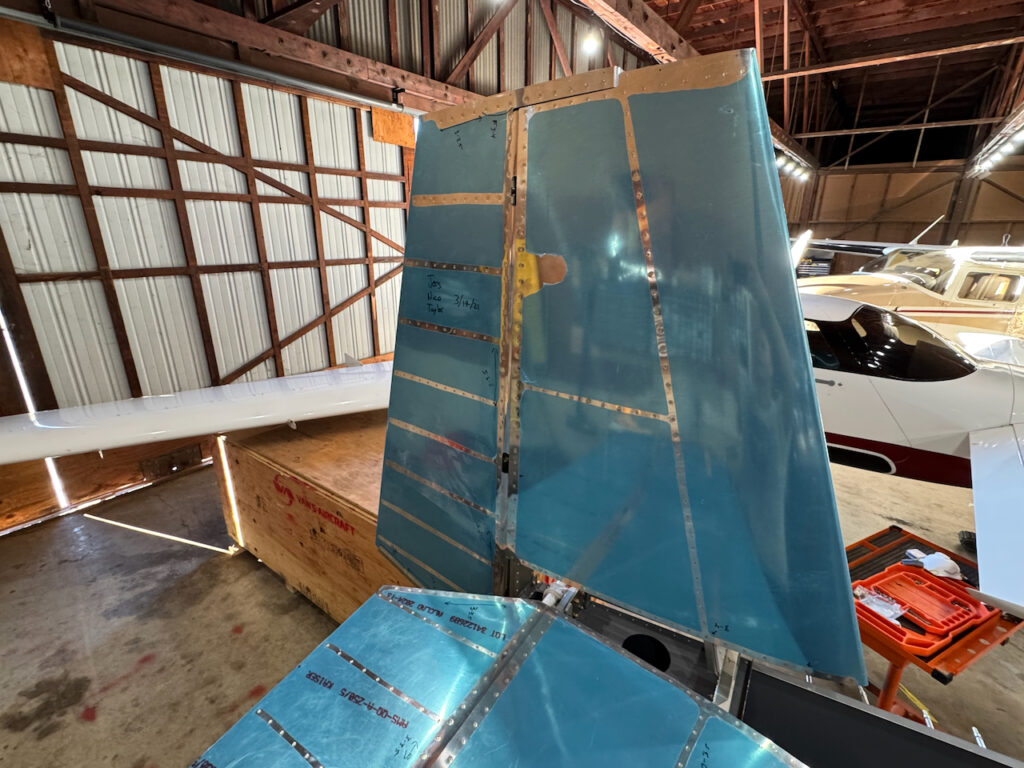
Looks AMAZING!
WOW WOW WOW!
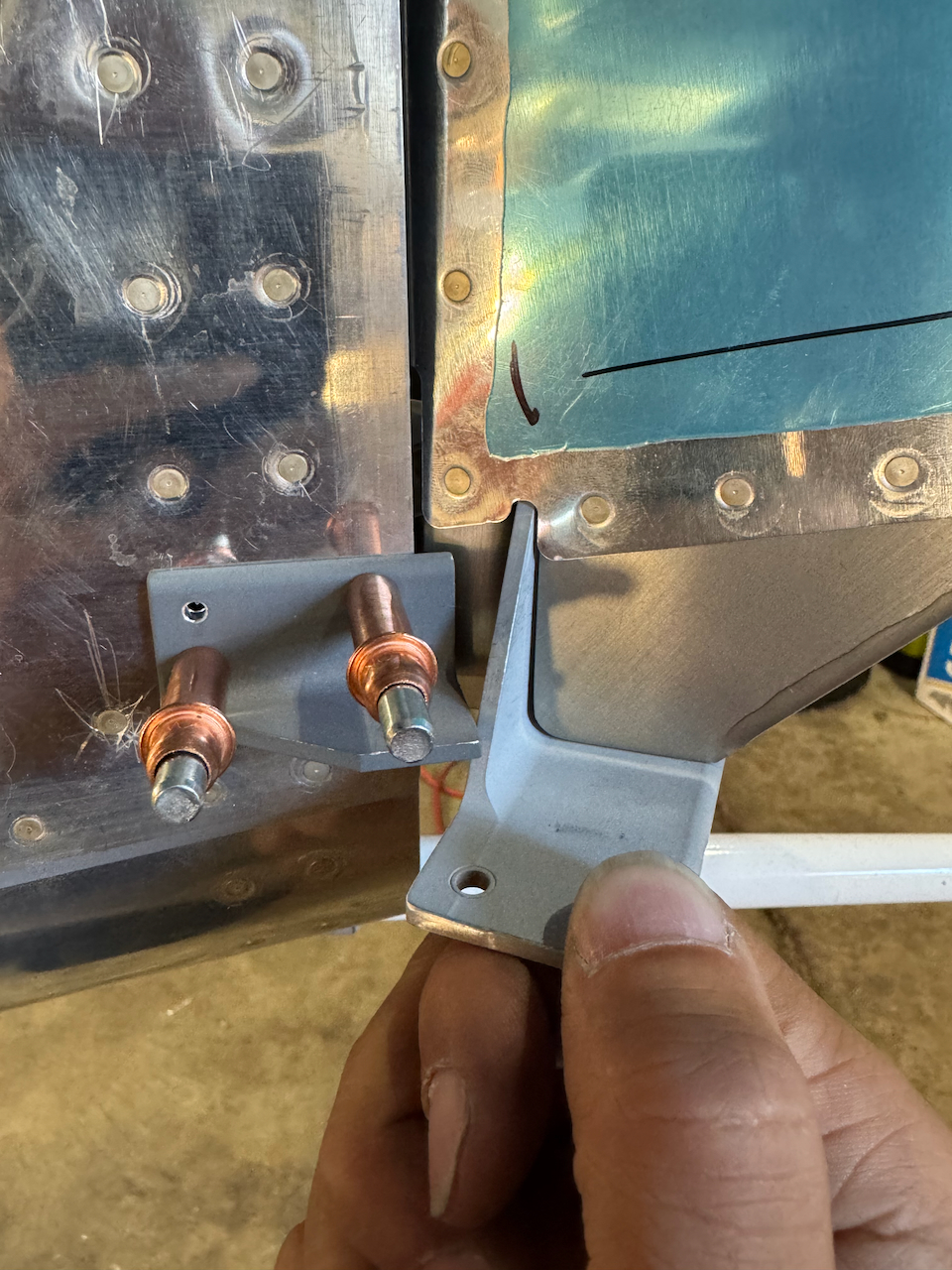
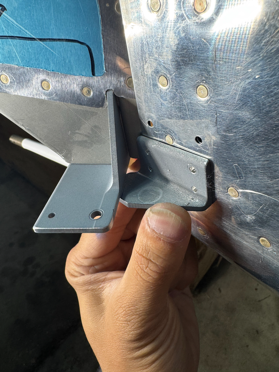
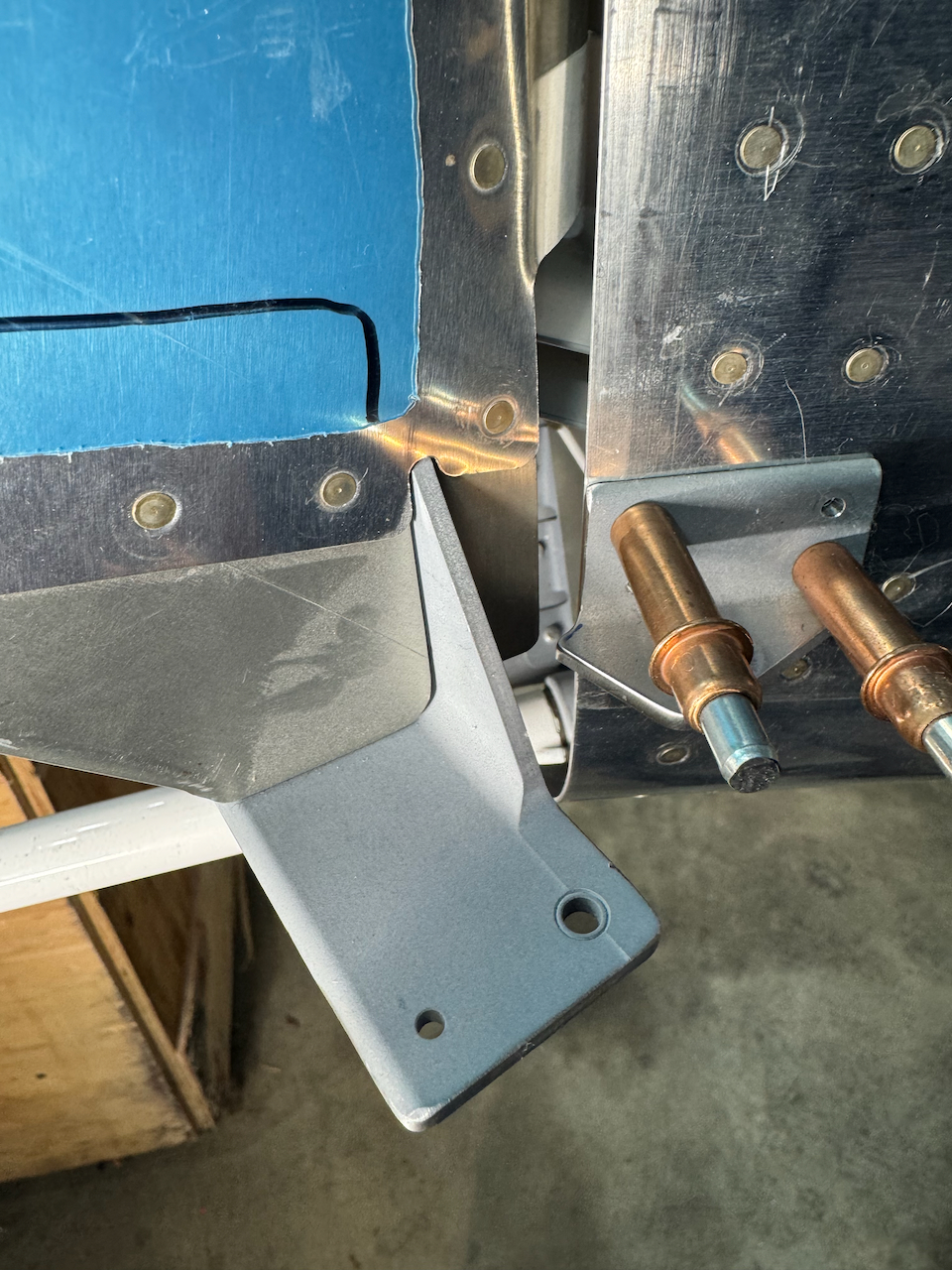
uncut rudder stop installed
makeshift stop to ensure proper clearances
plans reccomend sliding stop down to mark properly
initial trim looks good.
continued trimming until satisfactory deflection
right looks good!
left looks good!
stops re-primed and drying before install.
Next up will be finishing up the elevator down stop once I get the stock material, and then it’s on to rudder cables and rudder pedals… At that point I might need to get in the cockpit and make some airplane noises!!! Until then… Happy Building!